Waste paper basket

Inactive Publication Date: 2005-04-21
TEST RITE INT
View PDF4 Cites 38 Cited by
  • Summary
  • Abstract
  • Description
  • Claims
  • Application Information

AI Technical Summary

Problems solved by technology

No prior art has disclosed the incorporation of a roller into a waste paper basket.

Method used


Image

  • Waste paper basket
  • Waste paper basket
  • Waste paper basket

Examples


Embodiment Construction

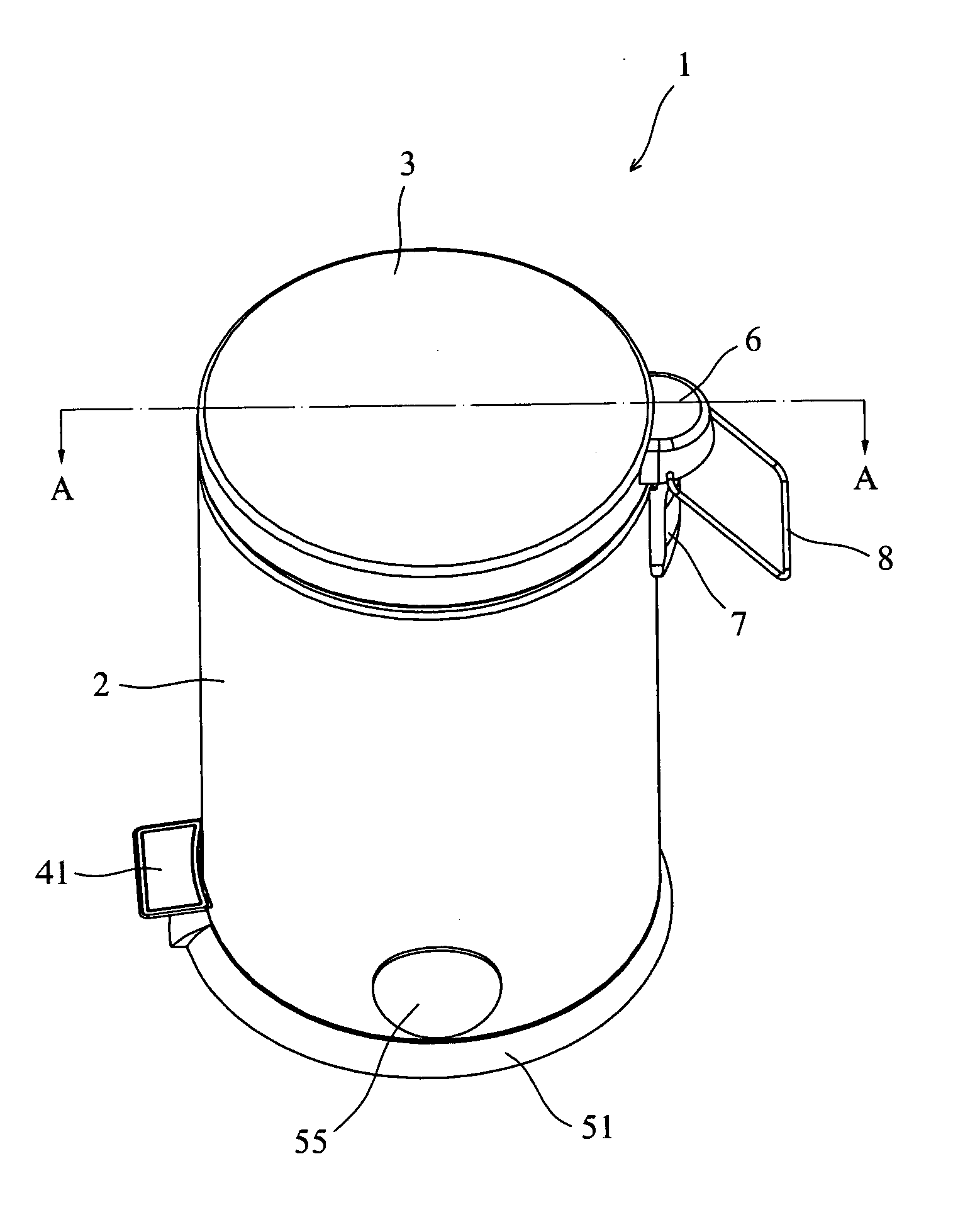
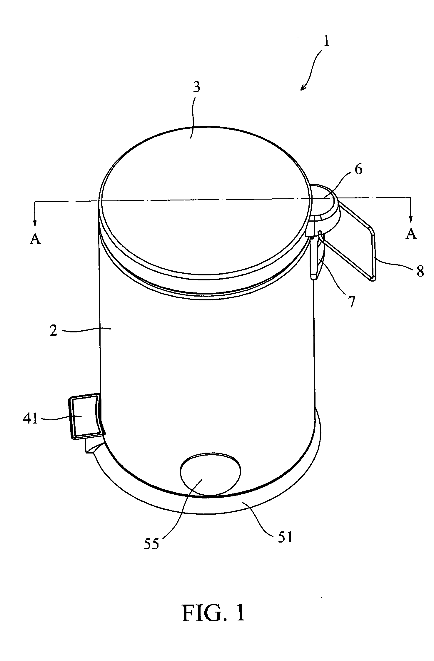
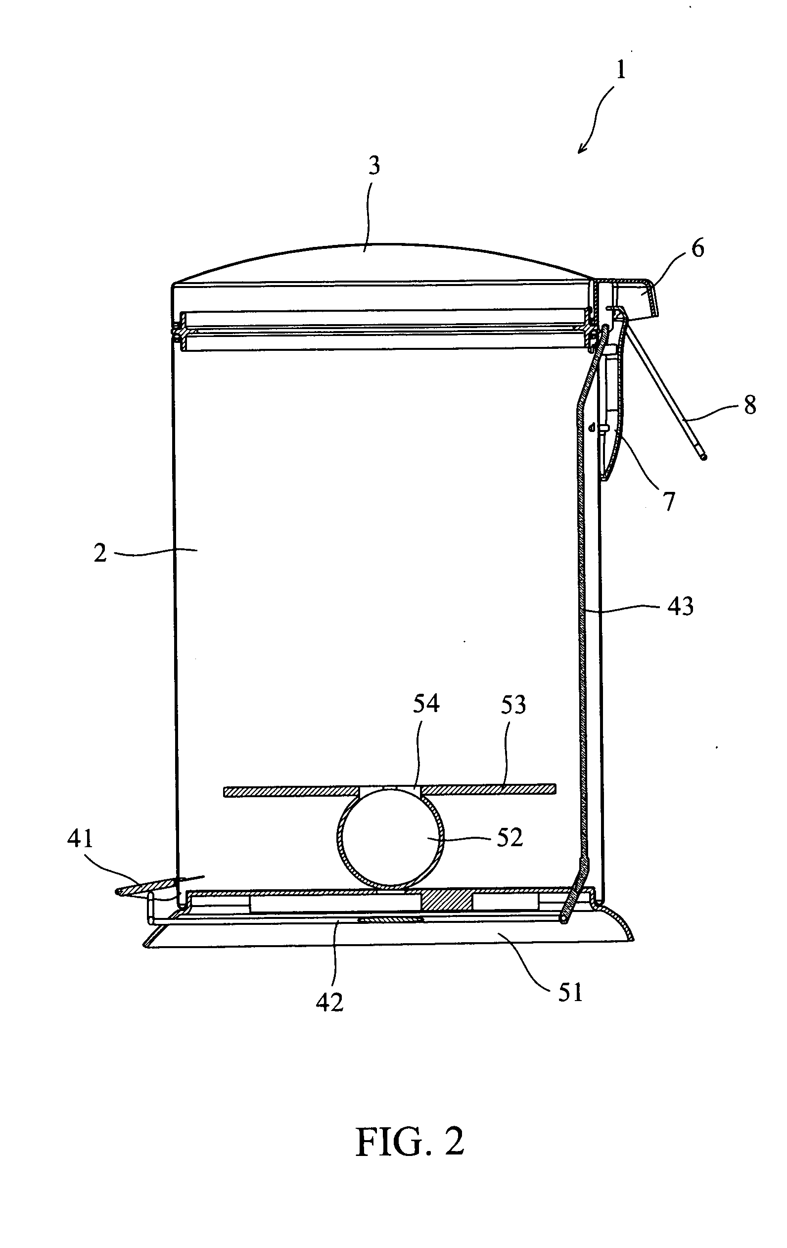
[0012] As shown in FIG. 1 and FIG. 2, wherein a longitudinal cross sectional view of a waste paper basket 1 of the present invention in FIG. 2 is made with reference to a basket base 5, a pedal unit 4, a pivotal portion 6 and a fixation portion 7 to show the cross sectional view of the waste paper basket 1. The waste paper basket 1 of the present invention comprises: a body 2, a lid 3, a pedal unit 4, a basket base 5, a pivotal portion 6, a fixation portion 7 and a handle 8; the pedal unit 4 comprises a pedal 41, a linkage 42 and a rod 43; the basket base 5 comprises a base 51, a roller 52 and a supporting base plate 53; the body 2 is fastened on the base 51; the lid 3 is sleeve jointed to the body 2; the pedal 41 is plugged into one end of the linkage 42; another end of the linkage 42 is apically joined to one end of the rod 43; another end of the rod 43 is connected to the fixation portion 7; the handle 8 is plugged into the pivotal portion 6, which is connected to the fixation po...


PUM


Abstract

A waste paper basket comprises a body, a lid, a pedal unit, a basket base, a pivotal portion, a fixation portion and a handle. The pedal unit comprises a pedal and a linkage; the basket base comprises a base, a roller and a supporting base plate; the body is fastened on the basket base; the lid is sleeve jointed to the body; the linkage is connected to the pedal and the fixation portion; the handle is plugged into the pivotal portion, which is connected to the fixation portion and assembled on the external periphery of the junction of the lid and the body. A roller cap passes through a hole of the body and then is sleeve jointed to the roller. It is possible to place waste bags inside the roller of the waste paper basket in advance, so that when the waste bag on the supporting base plate is taken out for disposal, a new waste bag is drawn out from the roller along with the old waste bag.

Description

FIELD OF THE INVENTION [0001] The present invention relates to a waste paper basket, and more particularly to an improved waste paper basket that is capable of automatically drawing out waste bags. BACKGROUND OF THE INVENTION [0002] Commonly used waste paper baskets are generally available in two designs, namely, the open type and the closed type. The closed-type waste paper basket is constructed by assembling a top-supporting rack on the back of a basket body, and one lower end of the top-supporting rack is pivotally connected to one end of a pedal disposed on a bottom side of the basket body as an integrated unit; moreover, one upper end of the top-supporting rack is pivotally connected to a lid of the waste paper basket at a suitable location to be used as a pivot as a whole, such that when a user presses down the pedal installed on the lower end of the basket body by foot, top-supporting rack rises upward and actuates the lid to be lifted open upward, until the top-supporting ra...

Claims


Application Information

Patent Timeline
Patent Type & Authority Applications(United States)
IPC IPC(8): B65F1/06B65F1/16
CPCB65F1/062B65F2230/15B65F1/163
Inventor LIN, DAPHNE
Owner TEST RITE INT
Why Eureka
Try Eureka