
Front suspension for vehicles with front steerable wheel

a technology of front suspension and steerable wheel, which is applied in the direction of steering device, cycle equipment, friction roller based transmission, etc., can solve the problem of increasing the total mass of unsprung elements, and achieve the effect of reducing the “vehicle diving”

Inactive Publication Date: 2005-04-21
BWI CO LTD SA
View PDF9 Cites 7 Cited by
  • Summary
  • Abstract
  • Description
  • Claims
  • Application Information

AI Technical Summary

Benefits of technology

"The present invention provides a front suspension for a vehicle with a front steerable wheel that has a minimal mass of unsprung suspension elements. The front suspension allows for the vehicle position stabilization by the appropriate transmission of the inertial forces which occur during braking or accelerating of the vehicle. The front suspension includes a pull rod connected at one end to the upper part of the front wheel fork, able to shift in relation to the fork column of the handle bar, and at the other end to the elastic element and / or the damping element, supported on at least one end by the vehicle frame. The pull rod goes through the handle bar steering axis. The invention also includes a front suspension that allows for the coupling of the front and rear suspension shifts to reduce the \"vehicle diving\" during braking or lifting the front wheel during rapid acceleration. The pull rod is made of a flexible material that takes part in amortization and dissipation of vibration energy."

Problems solved by technology

However, in typical constructions of telescopic forks, the total mass of unsprung elements is increased by the weight of the spring and the damper.

Method used


Image

  • Front suspension for vehicles with front steerable wheel
  • Front suspension for vehicles with front steerable wheel
  • Front suspension for vehicles with front steerable wheel

Examples


Embodiment Construction

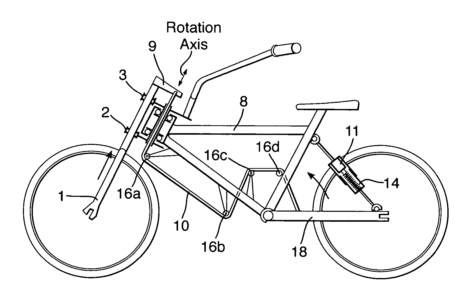
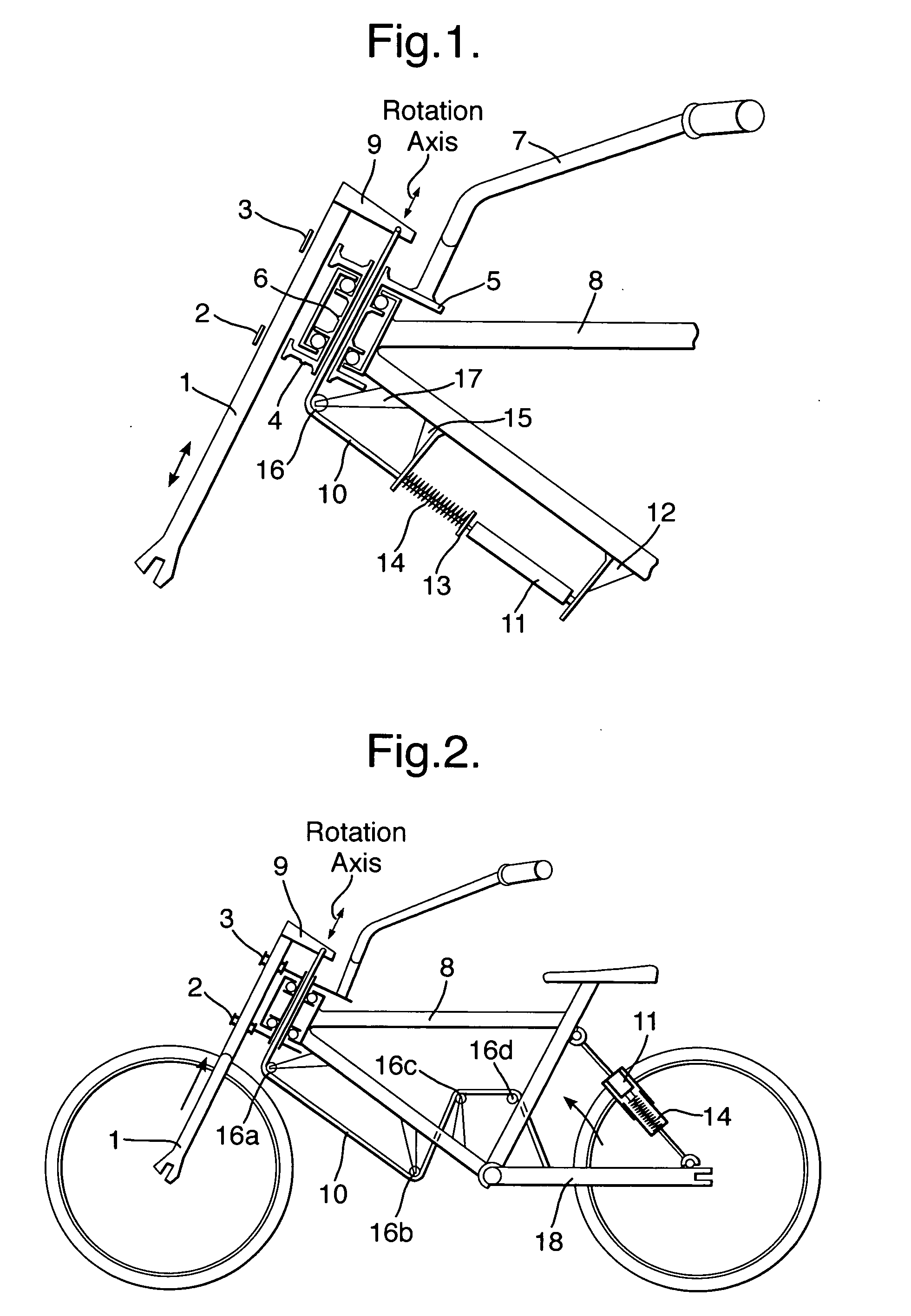
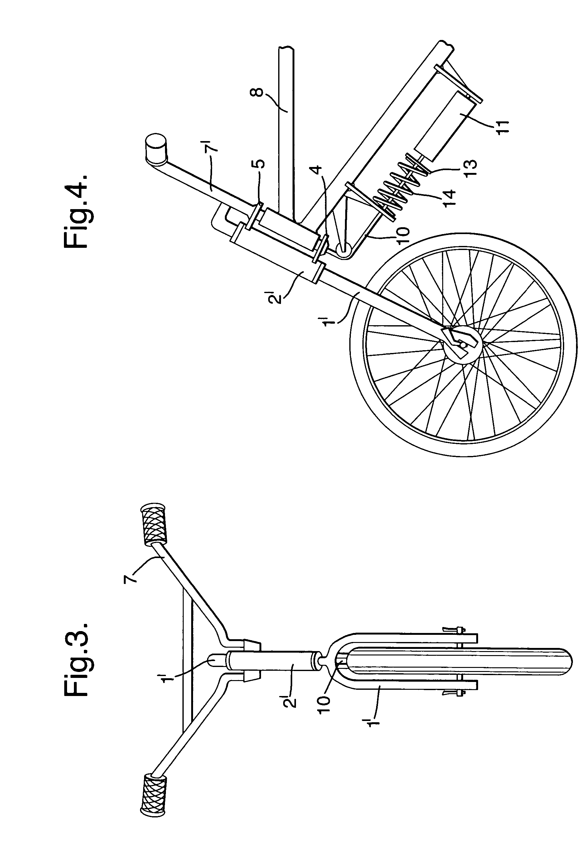
[0028] As shown in FIG. 1, fork 1 comprises two tubes adapted for holding a front steering wheel of a vehicle (not shown). Each of the fork tubes is stabilized and slidingly received in a bottom sleeve 2 and an upper sleeve 3. The sleeves contain appropriate friction reducing materials between the fork tubes, for example, slide linings or rolling elements. The bottom sleeve 2 and the upper sleeve 3 are mounted to the bottom support 4 and the upper support 5 connected to the fork column 6 of the handle bar 7 of the vehicle. The fork column 6 is fixed in the known way to the frame 8 of the vehicle.

[0029] Above the upper sleeve 3, the fork tubes are connected to the support 9 to which one end of a pull rod 10 is attached, which pull rod may be a steel line or cable. The other end of pull rod 10 is connected to the piston rod of a damping element 11 connected to a support 12 mounted on frame 8 of the vehicle. Pull rod 10 is also attached to a resistance plate supporting an elastic elem...


PUM


Abstract

The present invention relates to the front suspension containing elastic (14) and damping (11) elements, for vehicles with front steerable wheel, such as bicycles, motor-bicycles, motorcycles or tricycles. To minimise the total mass of the unsprung suspension elements, by relocating the elastic and the damping elements to the springing side, the suspension contains at least one pull rod (10) connected at one end to the upper part of the front wheel fork (1), able to shift in relation to the fork column (6) of the handle bar (7), and at the other end to the elastic element (14) and / or the damping element (11), supported on at least one end by the vehicle frame (8), wherein the pull rod (10) goes through the handle bar (7) steering axis. The pull rod (10) is preferably led on at least one leading element (16) supported by the vehicle frame. Optionally, the pull rod (10) may be connected on the other end to the fork (18) of the vehicle rear suspension.

Description

TECHNICAL FIELD [0001] The present invention relates to a front suspension containing elastic and damping elements, for vehicles with front steerable wheel, such as bicycles, motor-bicycles, motorcycles or tricycles. BACKGROUND OF THE INVENTION [0002] In designing bicycles and the like, it is normally the aim of the designing process to minimise the total mass of unsprung suspension elements placed on the wheel side of the vehicle, along with the wheel. This is caused by the need of decreasing the front fork tensions which are transmitted onto the steering column during riding on rough roads. However, in typical constructions of telescopic forks, the total mass of unsprung elements is increased by the weight of the spring and the damper. [0003] In U.S. Pat. No 5,749,590 a front suspension is presented where the elastic and the damping elements are placed in the steering column and controlled by a multiple link pivot mounting mechanism. As a result, the mass of the fork was reduced, ...

Claims


Application Information

Patent Timeline
Patent Type & Authority Applications(United States)
IPC IPC(8): B62K21/02B62K21/20
CPCB62K21/20B62K21/02
Inventor MYDLARZ, JERZY
Owner BWI CO LTD SA
Learn More