Method and apparatus for image forming capable of effectively eliminating color displacements

Active Publication Date: 2005-04-21
RICOH KK
View PDF28 Cites 61 Cited by
  • Summary
  • Abstract
  • Description
  • Claims
  • Application Information

AI Technical Summary

Benefits of technology

[0019] An object of the present invention is to provide a novel image forming apparatus which can control a clock

Problems solved by technology

In a case where the photoconductor rotates at a different rate from the intermediate transfer member, a surface of the photoconductor rubs a surface of the intermediate transfer member, hastening their surface wear.
The stepping motor, however, generally consumes a large amount of electric power and produces a loud noise.
The DC brushless motor, however, may vary its rotation speed particularly when it is started and stopped.
In a case where the DC brushless motor is used as the photoconductor motor and the drive motor, the surface linear velocity of the photoconductor may be greatly different from that of the intermediate transfer member or that of th

Method used


Image

  • Method and apparatus for image forming capable of effectively eliminating color displacements
  • Method and apparatus for image forming capable of effectively eliminating color displacements
  • Method and apparatus for image forming capable of effectively eliminating color displacements

Examples


Embodiment Construction

[0091] In describing preferred embodiments illustrated in the drawings, specific terminology is employed for the sake of clarity. However, the disclosure of this patent specification is not intended to be limited to the specific terminology so selected and it is to be understood that each specific element includes all technical equivalents that operate in a similar manner.

[0092] Referring now to the drawings, wherein like reference numerals designate identical or corresponding parts throughout the several views, preferred embodiments of the present invention are described.

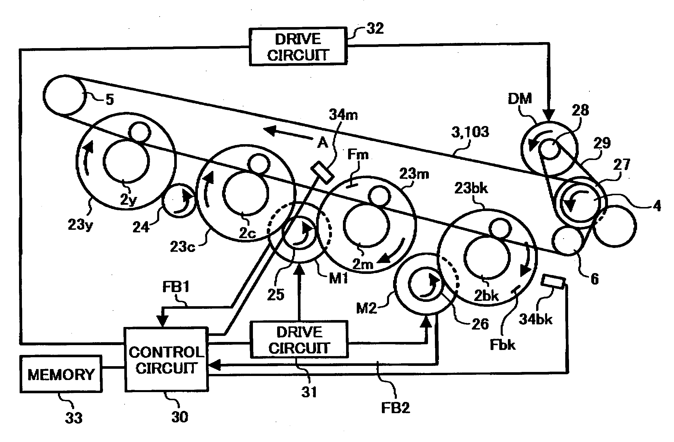
[0093]FIG. 5 shows a schematic cross sectional view of an image forming apparatus 1. The image forming apparatus 1 of FIG. 5 is a printer using an intermediate transfer method. The-image forming apparatus 1 includes four photoconductors 2y, 2c, 2m and 2bk, and an intermediate transfer member 3. The photoconductors 2y, 2c, 2m and 2bk are in a cylindrical shape, and have an outer diameter. The intermediate transfer ...


PUM


Abstract

An image forming apparatus including at least one image bearing member configured to bear a toner image on a surface thereof, and a transferring member arranged close to or in contact with the at least one image bearing member and configured to rotate in substantially synchronism with the at least one image bearing member to transfer the toner image born on the at least one image bearing member onto a recording medium. The apparatus further includes at least one first motor rotating the at least one image bearing member, a second motor rotating the transferring member, and a control mechanism configured to control a rotation number of at least one of the at least one first motor and the second motor during at least one of rise and fall time periods with a command clock signal and a feedback signal in accordance with a predetermined velocity curve.

Description

CROSS REFERENCE TO RELATED APPLICATIONS [0001] The present application claims priority under 35 U.S.C. § 119 to Japanese Patent Applications No. 2003-192821. filed on Jul. 7, 2003, No. 2003-408291 filed on Dec. 5, 2003, and No. 2004-114717 filed on Apr. 8, 2004 in the Japanese Patent Office, the entire contents of which are incorporated herein by reference. BACKGROUND OF THE INVENTION [0002] 1. Field of the Invention [0003] The present invention relates to an image forming method and apparatus, and more particularly to a method and apparatus for image forming capable of effectively eliminating color displacement by controlling a clock control motor controlled by a command clock signal and a feedback signal, in accordance with a velocity curve. [0004] 2. Discussion of the Background [0005] Background image forming apparatuses are commonly known as electrophotographic copying machines, printing machines, facsimile machines, and multi-functional apparatuses having at least two function...

Claims


Application Information

Patent Timeline
IPC IPC(8): G03G15/00G03G21/00G03G15/01H02P5/74
CPCG03G15/5008G03G2215/00075G03G2215/0158G03G2215/0132G03G2215/0148G03G2215/0119
Inventor FUKUCHI, YUTAKAKUMA, KAZUOSAKIKURA, MAKOTONOGUCHI, YUUSUKEISHII, HIROSHISUZUKI, KAZUKIEBARA, JOHUCHIDA, TOSHIYUKIFUNAMOTO, NORIAKI
Owner RICOH KK
Why Eureka
Try Eureka