Combination of electrical connectors

a technology of electrical connectors and connectors, applied in the direction of coupling device details, coupling device connections, electric discharge lamps, etc., can solve the problems of high cost and more expense expenditure, and achieve the effect of simple and economical methods

Inactive Publication Date: 2005-04-21
COMAX TECH
View PDF5 Cites 2 Cited by
  • Summary
  • Abstract
  • Description
  • Claims
  • Application Information

AI Technical Summary

Benefits of technology

[0006] It is therefore a primary object of the invention to provide a combination of electrical connectors that offers a simple and economical method to have two connectors connected in parallel after combination.

Problems solved by technology

Heretofore, it is known that the connectors applied on computer main boards are usually single type and independent of each other; however, technology advances, many interfaces and connectors keep expanding, many manufacturers modify their molds that causes more expense spending.
549640 applies a fixed frame to combine two connectors, the design solves most of the issues to combine connectors, however the design is very complex, the mold design is a huge task; while manufacturing, the products are not easy to meet the original design, out of shape is a big issue, the cost becomes very high to be economical.

Method used


Image

  • Combination of electrical connectors
  • Combination of electrical connectors
  • Combination of electrical connectors

Examples


Embodiment Construction

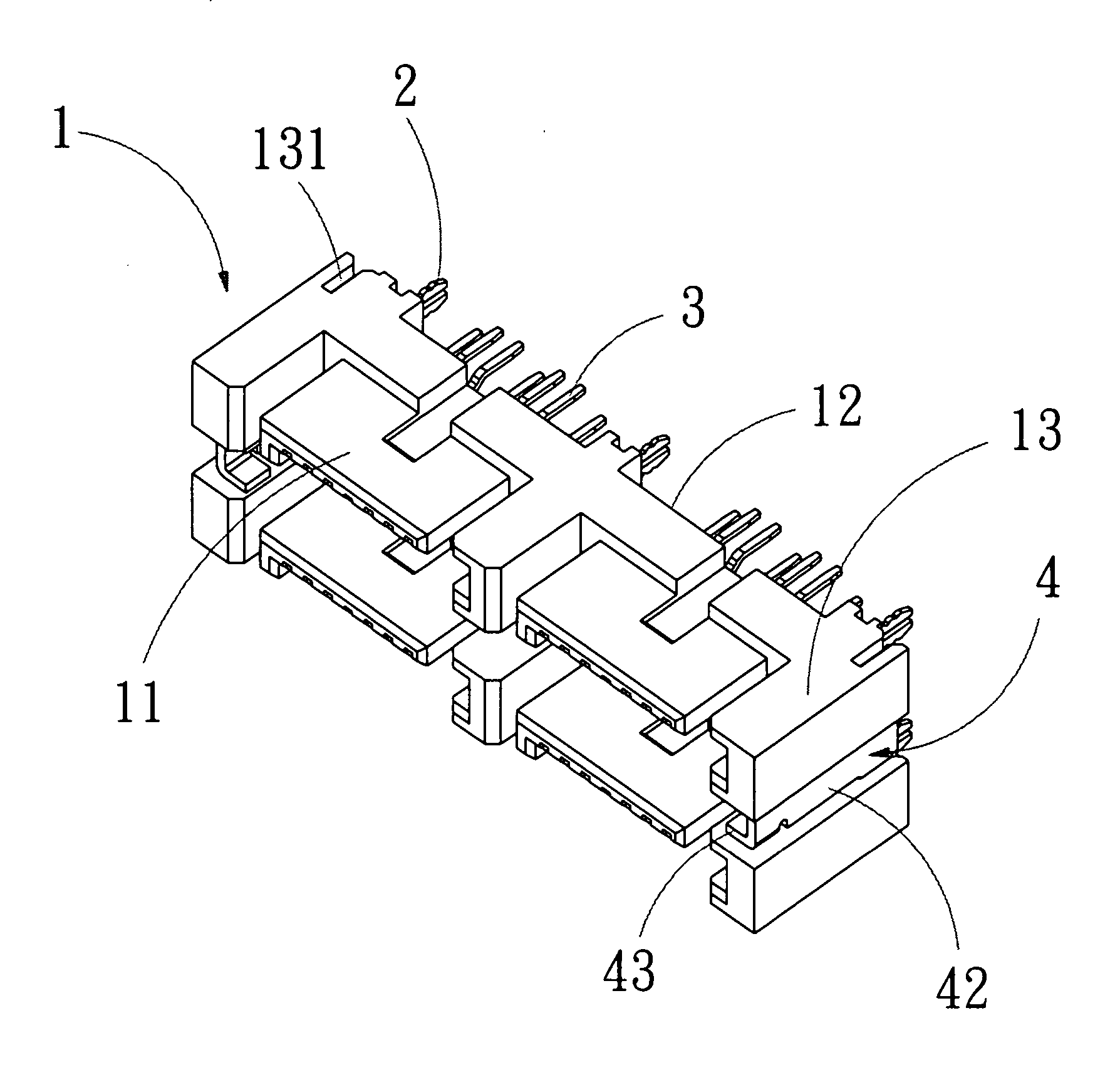
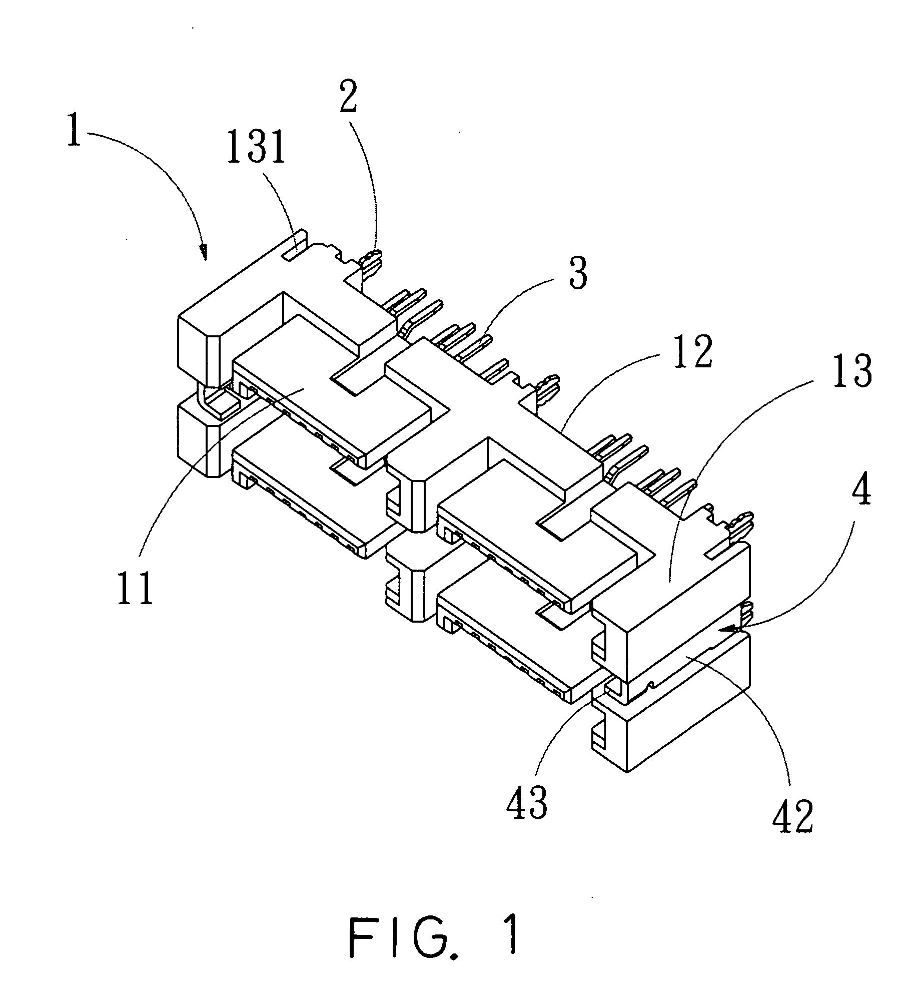
[0012] Referring to FIG. 1, the application of the present invention, a connecting part 4 each is installed on front, back or the proper location, such as one sidewall 13 of the connector 1 to have the two connectors 1 connected in parallel after combination.

[0013] The connector 1 consists of a transmission portion 11 and a fastening portion 12; the connector 1 also has a definite number of fastening units 2 and a plurality connecting pins 3.

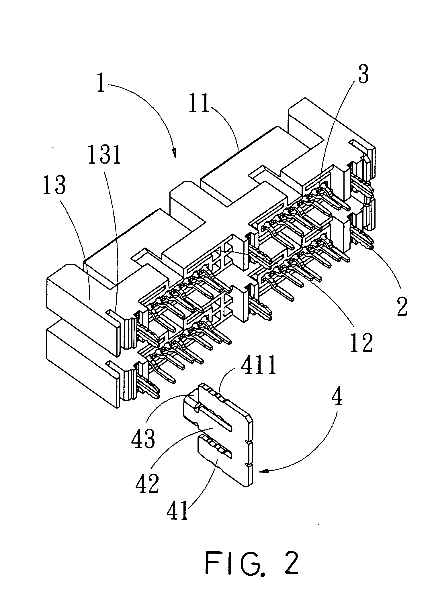
[0014] Referring to FIG. 2 and FIG. 3 shows an assembly view and a cross-sectional view of the present invention, two inserting portions 41 are installed horizontally on two sides of the connecting part 4 to be inserted into the inserting slots 131 of the sidewall 13 of the connector 1.

[0015] Two teeth portion 411 are on both side walls of the inserting portion 41 to fix the connector 1 and the connecting part 4 firmly together, a partition 42 is between two inserting portions 41 to have two connectors 1 maintain certain distance.

[0016] In o...


PUM


Abstract

A combination of electrical connectors comprising a connecting part each is installed on front, back or the proper location, such as one sidewall of the connector to have the two connectors connected in parallel after combination; two inserting portions are installed horizontally on two sides of the connecting part to be inserted into the inserting slots of the sidewall of the connector; a partition is between the two inserting portions to have two connectors maintain certain distance.

Description

BACKGROUND OF THE INVENTION [0001] I. Field of the Invention [0002] This invention relates generally to a combination of electrical connectors and, more specifically, to a combination of electrical connectors that has a connecting part each is installed on front, back or the proper location of the connector to have the two connectors connected in parallel after combination, a partition on the connecting part is located between the connector to have two connectors maintain certain distance. [0003] II. Description of the Prior Art [0004] Heretofore, it is known that the connectors applied on computer main boards are usually single type and independent of each other; however, technology advances, many interfaces and connectors keep expanding, many manufacturers modify their molds that causes more expense spending. [0005] Some researches such as a Taiwanese pattern no. 549640 applies a fixed frame to combine two connectors, the design solves most of the issues to combine connectors, how...

Claims


Application Information

Patent Timeline
Patent Type & Authority Applications(United States)
IPC IPC(8): H01R12/00H01R33/88
CPCH01R13/518H01R13/514
Inventor CHAI, CHIA-YENCHOU, FU-CHENCHEN, PI-CHING
Owner COMAX TECH
Why Eureka
Try Eureka