
Metal picture frame with dust cover

Inactive Publication Date: 2005-05-05
NIELSEN & BAINBRIDGE L L C
View PDF5 Cites 3 Cited by
  • Summary
  • Abstract
  • Description
  • Claims
  • Application Information

AI Technical Summary

Problems solved by technology

Ordinarily the dust cover can readily be attached adhesively to the back of a frame, but in the case of a conventional metal frame as described above, it is difficult to attach the dust cover to the back of the frame because there is only a relatively small area to which the dust cover can be adhered.
Moreover, because of the dimensions of the frame section, it is difficult to apply an adhesive tape to the back of the frame using conventional adhesive tape guns.

Method used


Image

  • Metal picture frame with dust cover
  • Metal picture frame with dust cover

Examples


Embodiment Construction

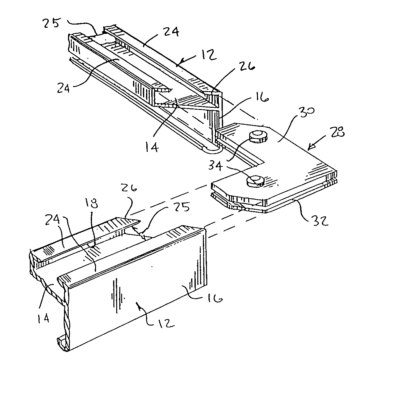
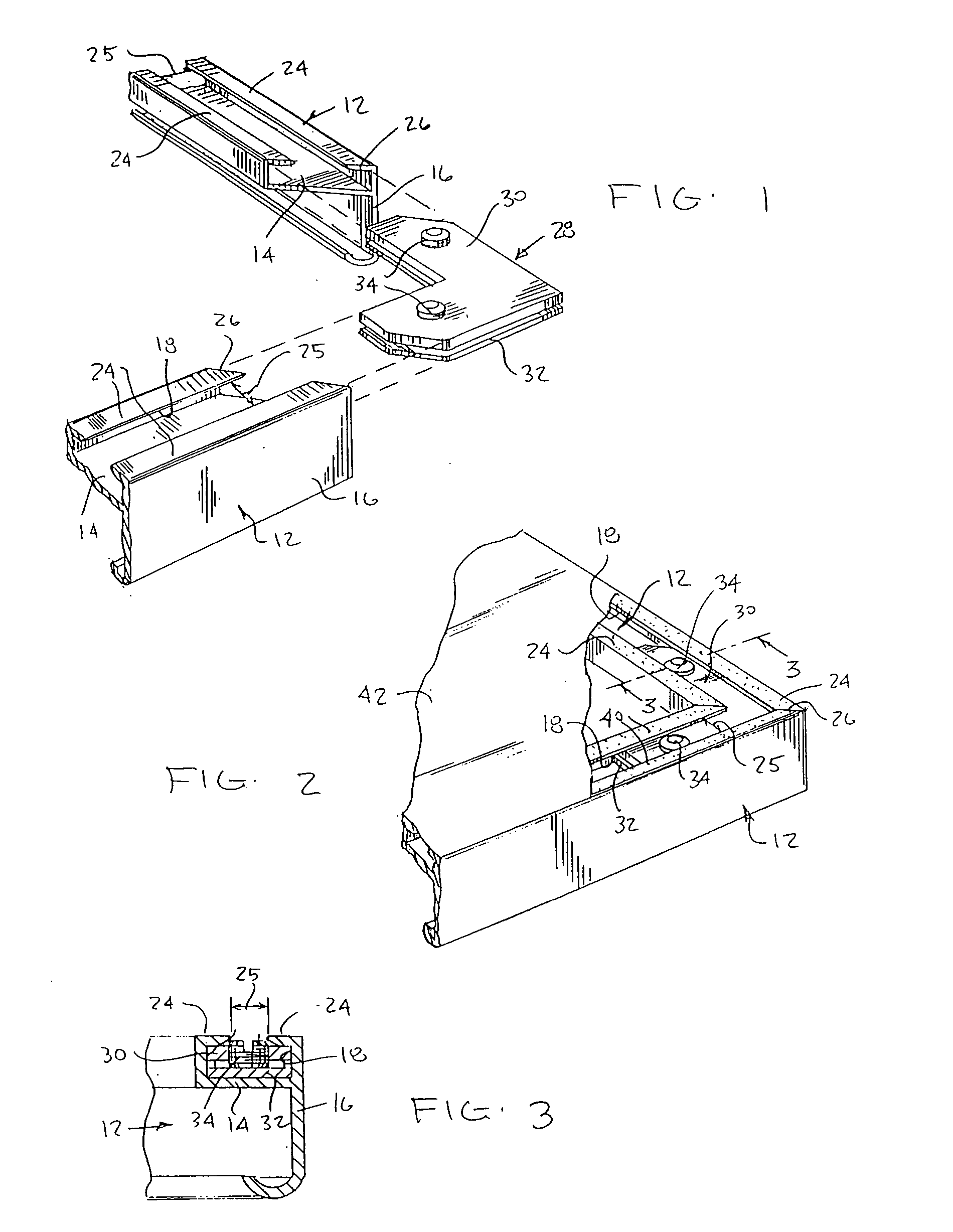
[0008] A picture frame comprises four frame sections 12 preferably extruded from aluminum. The frame sections 12 have identical cross sections and, as shown in FIG. 1, include an inwardly directed supporting flange 14, an outer wall 16 and a receiving channel 18. The receiving channel 18 is rectangular in cross section and includes two opposed lips 24 which are spaced apart to define a gap 25 extending the length of each section.

[0009] The ends of each section are mitered as illustrated at 26 and adjacent frame sections are joined together at their mitered ends and secured in place by a corner piece 28. The corner piece 28 includes an L-shaped screw plate 30 and an L-shaped backing plate 32. Screw plate 30 includes two threaded holes, one in each leg, which receive set screws 34. Tightening of the set screws 34 forces the plates 30 and 32 apart thereby clamping the adjacent frame sections 12 together.

[0010] The gap 25 between the edges of the lips 24 at the back of the frame secti...


PUM


Abstract

In a picture frame formed of extruded metal sections, each section has a channel for receiving a portion of a corner piece. The corner piece has two L-shaped plates that fit into the receiving channel. A set screw accessible through a gap between two spaced-apart lips at the back of the frame is used to secure adjacent sections.

Description

FIELD OF THE INVENTION [0001] This invention relates to metal picture frames and, in particular, to a metal picture frame adapted to retain a dust cover on its rear surface. BACKGROUND OF THE INVENTION [0002] A metal picture frame in common use today comprises four extruded aluminum sections which are mitered and secured together by corner pieces which function as expansion clamps. Each corner pieces are L-shaped with each leg receivable within a channel in the back of a section of the frame. The corner piece includes a pair of set screws which are accessible from the back of the frame and can be tightened by the framer to clamp the sections together. [0003] It is frequently desirable to attach a dust cover, usually made of paper, to the back of a frame. Ordinarily the dust cover can readily be attached adhesively to the back of a frame, but in the case of a conventional metal frame as described above, it is difficult to attach the dust cover to the back of the frame because there i...

Claims


Application Information

Patent Timeline
IPC IPC(8): A47G1/10
CPCA47G1/10A47G1/102A47G1/101
Inventor HOUSSIAN, VAZGEN
Owner NIELSEN & BAINBRIDGE L L C
Learn More