Minimally invasive fixation system

a fixation system and minimally invasive technology, applied in the field of minimally invasive fixation system, can solve the problems of more trauma to the body and the possibility of interference between cannulas

Active Publication Date: 2010-07-20
SYNTHES USA
View PDF130 Cites 123 Cited by
  • Summary
  • Abstract
  • Description
  • Claims
  • Application Information

AI Technical Summary

Benefits of technology

[0009]An embodiment of a method for implanting a rod into a rod-receiving channel formed in the screw heads of the pedicle screws include attaching the screw to a lateral implant holder and moving the sleeve to retain the screw in the engagement portion formed at the distal end of the lateral implant holder. The lateral implant holder, screw and sleeve may be inserted into the body through an incision made in the patient's skin. Each sleeve preferably includes a tissue protection portion extending out from the body, the tissue protection portion being sized and configured to reduce the amount of interference with adjacent tissue protection portions. A driving mechanism may also be used to insert the screw into the bone, and the rod may be inserted through the incision and into the rod receiving channel formed in the screw head. Preferably, the rod is inserted into the body at a first position and is moved into a second position different from the first position as the rod is inserted into the screw head.

Problems solved by technology

For example, retractors generally cause more trauma to the body than expandable cannulas since retractors tend to stretch tissue from the skin down to the surgical site.
A major drawback of using multiple cannulas is that if the surgeon needs to reposition adjacent cannulas, the cannulas may interfere with one another.

Method used


Image

  • Minimally invasive fixation system
  • Minimally invasive fixation system
  • Minimally invasive fixation system

Examples


Embodiment Construction

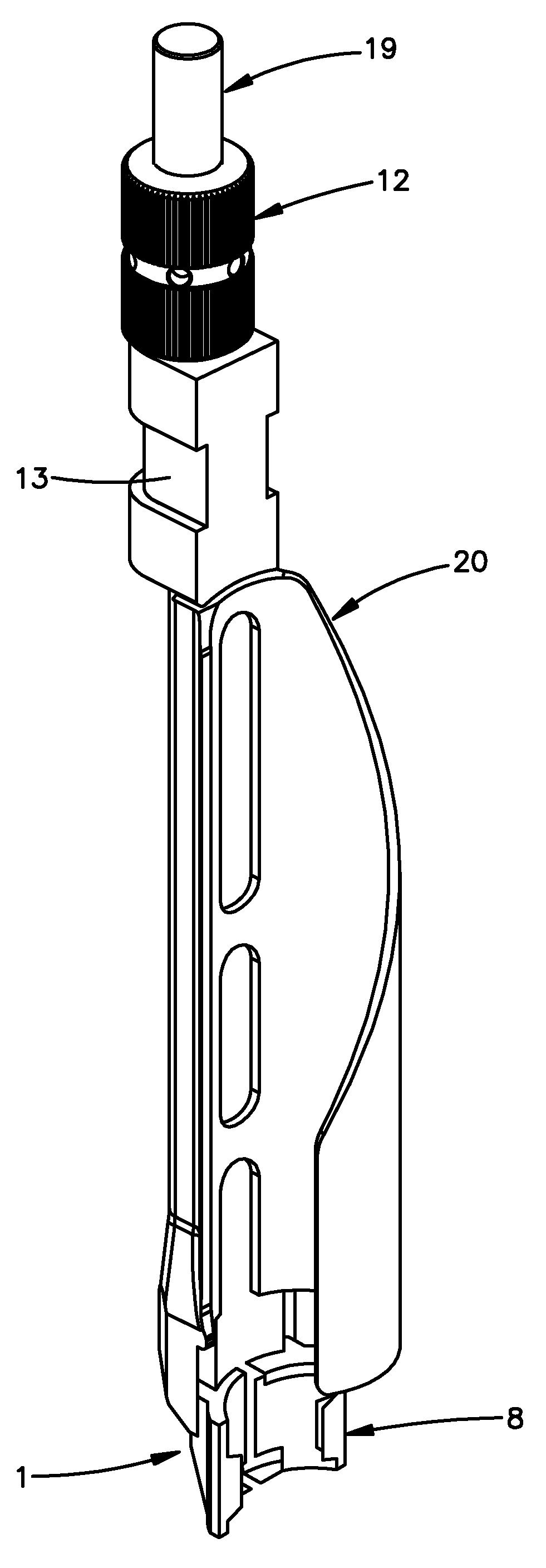
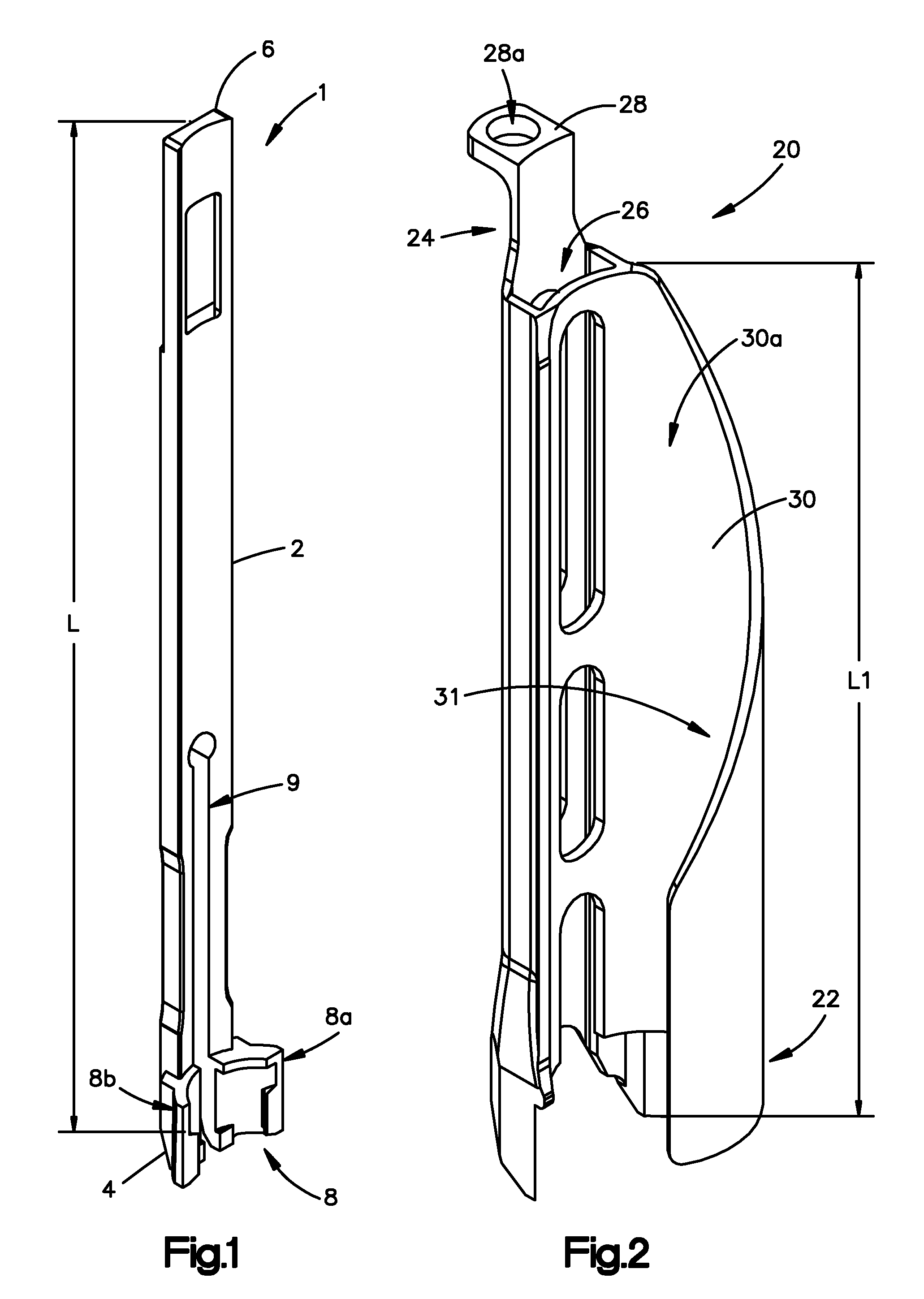
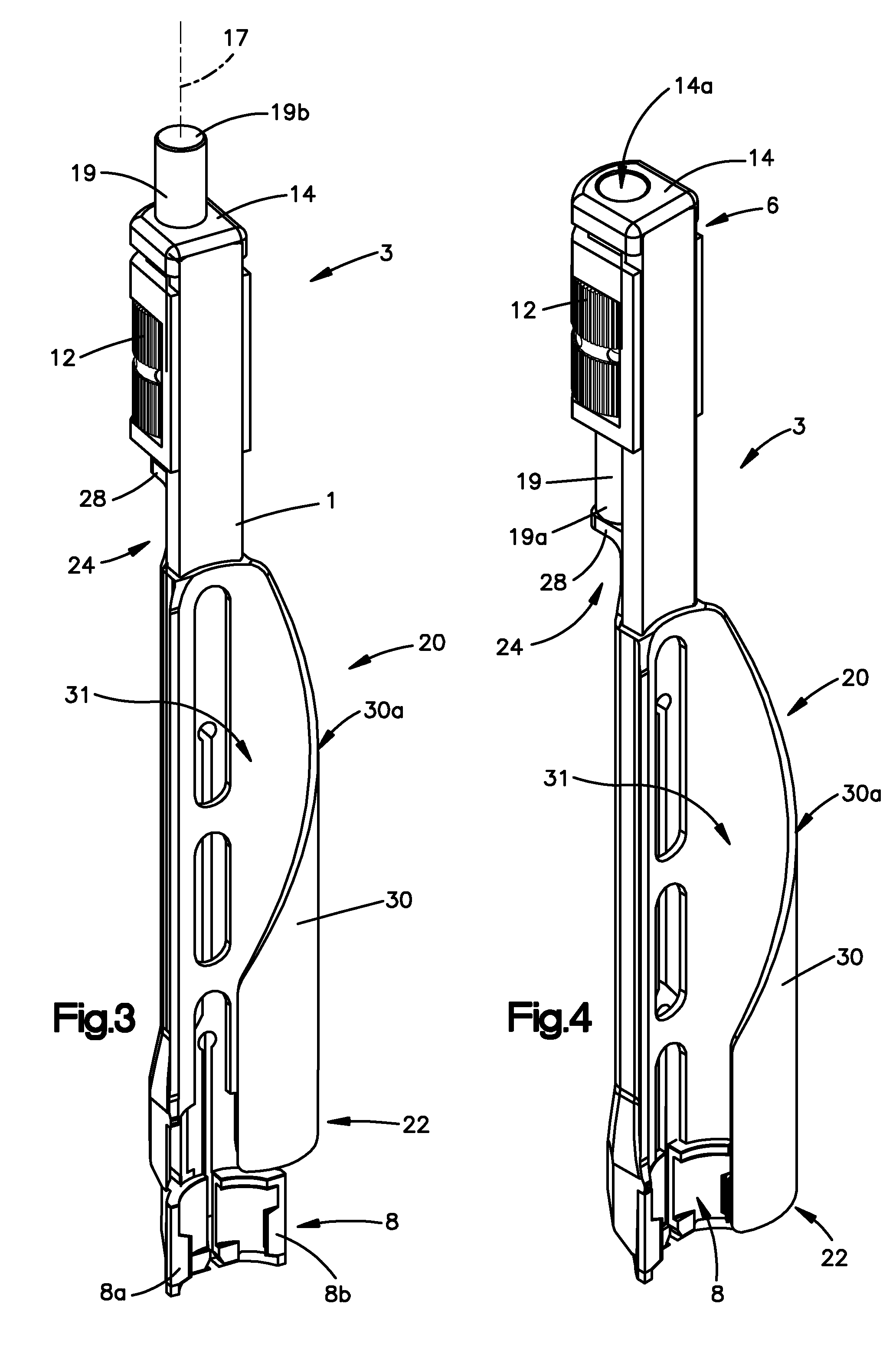
[0048]Certain exemplary embodiments of the invention will now be described with reference to the drawings. In general, such embodiments relate to a fixation system, by way of non-limiting example, a less invasive or minimally invasive fixation system for posterior spine fixation surgery using pedicle screws, preferably in the lumbar region of the spine. The fixation system including, for example, the implants and instruments are not limited to spine fixation, or posterior spine fixation and may have other uses and may come in different forms and structures. For example, the bone anchors are commonly shown and referred to as pedicle screws and may be polyaxial or mono-axial pedicle screw, as well as hooks (both mono-axial and polyaxial) or other fasteners, clamps or implants.

[0049]An embodiment of a fixation system in accordance with the present invention is directed to a minimally invasive system for posterior spinal fixation using pedicle screws, preferably in the lumber region of ...


PUM


Abstract

A minimally invasive fixation system and method for providing access to a surgical site. The fixation system may include a holding assembly, the holding assembling preferably including a lateral implant holder which may be attached to a pedicle screw and a sleeve positioned in connection with the lateral implant holder to prevent the lateral implant holder from separating from the pedicle screw. The sleeve may further include a tissue protection portion to keep the tissue out of the surgical site. A holding sleeve may be operably connected to the holding assembly and pedicle screw and may be used to insert the pedicle screw into the body. Multiple constructs may be inserted into the body so that a portion of the holding assembly extends from the body and provides access to and visualization of the surgical site. A rod holder may also be used to insert a rod into the head of the screw. The rod may be held by the rod holder so that the rod may be angulated as the rod is inserted into the screw heads. Once the rod is positioned in the screw heads, locking caps and / or set screws may be positioned over the rod and engage the screw heads so that the position of the rod may be fixed with respect to the screws. In some embodiments, a movement mechanism may be used to move the screws relative to each other to compress and / or distract the vertebrae.

Description

CROSS REFERENCE TO RELATED APPLICATION[0001]This application claims the benefit of U.S. Provisional Application No. 60 / 791,503 filed Apr. 11, 2006, the entire content of which is expressly incorporated herein by reference thereto.FIELD OF THE INVENTION[0002]The fixation system relates to a system for performing a less or minimally invasive surgery and, in particular, to a system for creating a passageway or access pathway or portal into a patient's body, preferably in the patient's spine and, preferably from a posterior direction for implanting a spinal fixation system to stabilize the patient's spine.BACKGROUND OF THE INVENTION[0003]It is known in the art to use retractors and / or cannulas to provide a surgeon with an access portal to a surgical site in a patient's body. In particular, retractors and / or cannulas may be used to perform spinal operations, for example, discectomies, laminectomies, facectomies, pedicle screw fixation, etc., such as in minimally invasive procedures.[0004...

Claims


Application Information

Patent Timeline
Patent Type & Authority Patents(United States)
IPC IPC(8): A61B17/58A61B17/60A61F2/00
CPCA61B17/7076A61B17/7082A61B17/7083A61B17/7079A61B17/00234A61B17/865A61B17/02A61B17/68A61B17/88A61B2090/034
Inventor BANKOSKI, BRIAN R.HANSON, SHAUNSOLITARIO, JR., RALPH C.BUNDRA, CARYN E.WOODBURN, SR., WILLIAM N.ROSSNEY, MARKMCDIVITT, ERICRATHBUN, DAVID
Owner SYNTHES USA
Why Eureka
Try Eureka