Eureka AIR delivers breakthrough ideas for toughest innovation challenges, trusted by R&D personnel around the world.

Retractable nacelle chine

a chine and nacelle technology, applied in the direction of airflow influencers, aircraft stabilisation, fuselages, etc., can solve the problems of reducing the overall utility of the aircraft, affecting the operating efficiency of the aircraft during cruise, takeoff and landing, and producing unwanted aerodynamic drag, so as to optimize the size, shape, orientation, position and quantity of the chine, the effect of reducing the aerodynamic drag

Active Publication Date: 2010-02-18
THE BOEING CO
View PDF13 Cites 48 Cited by
  • Summary
  • Abstract
  • Description
  • Claims
  • Application Information

AI Technical Summary

Benefits of technology

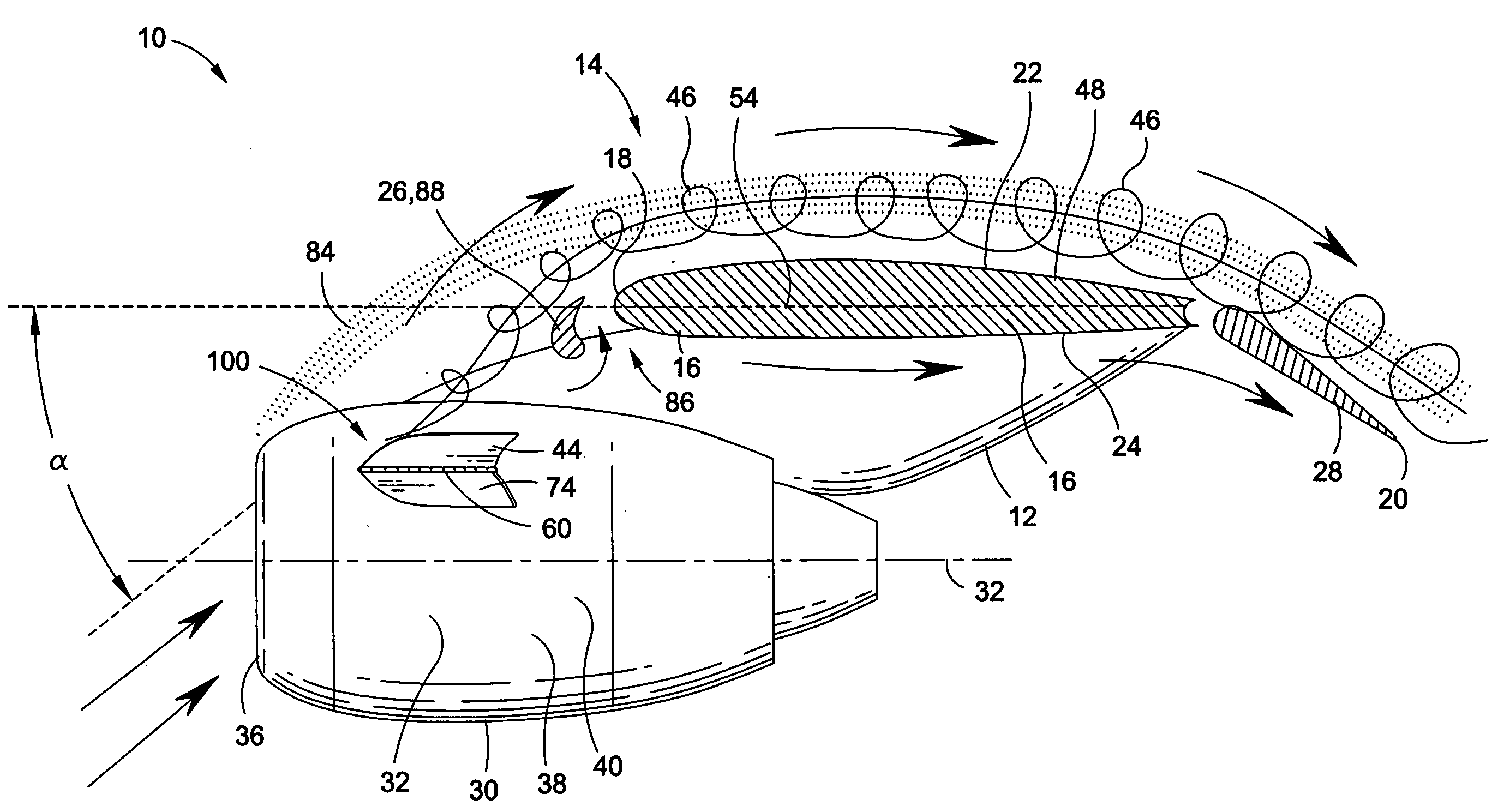
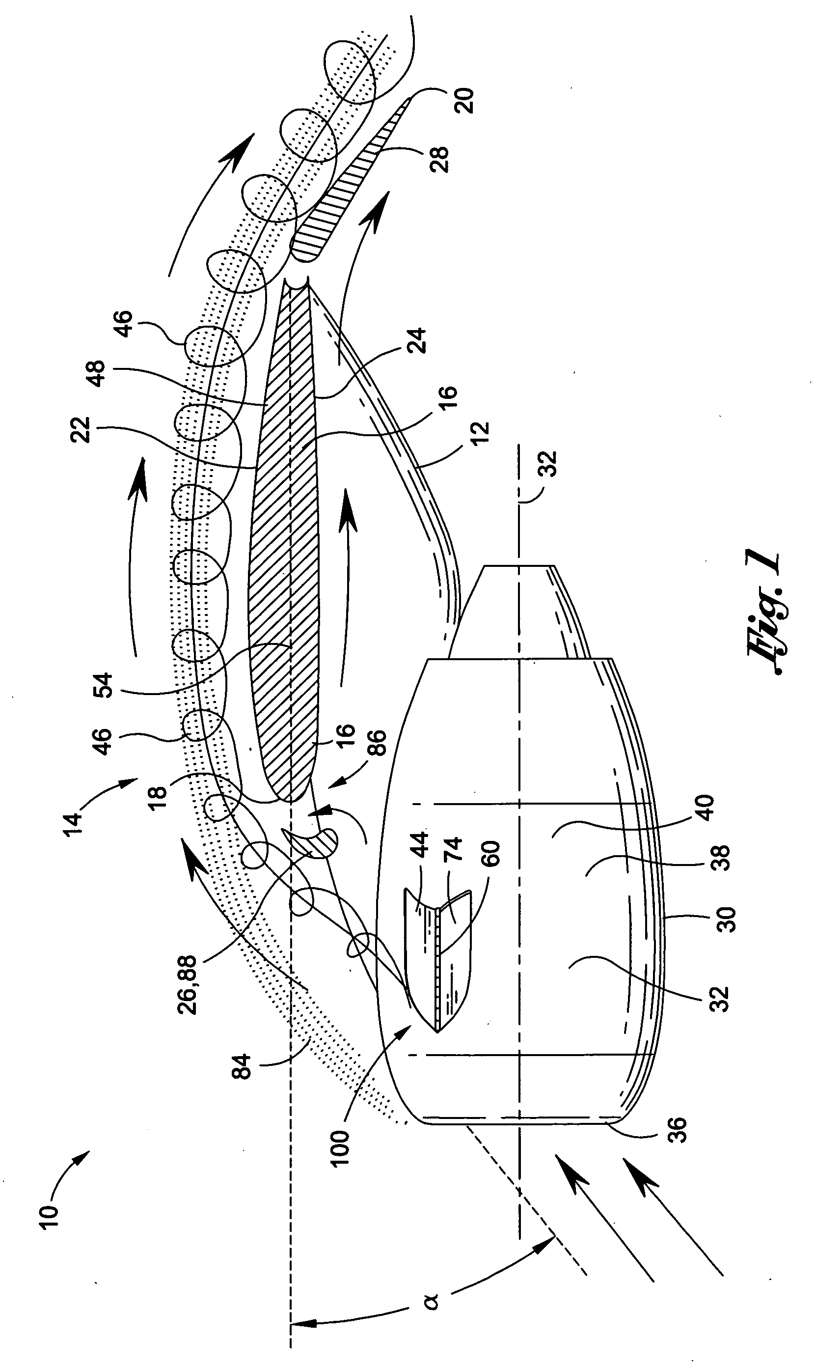
[0012]At high angles, the nacelle may generate a nacelle wake that passes over the wing upper surface and induces flow separation In this regard, the chine is preferably sized and positioned such that the vortex generated thereby interacts favorably with the nacelle wake in order to delay flow separation and thereby delay stall. The vortex produced by the chine thereby improves maximum lift capability by interacting with the boundary layer of the wing.
[0016]As was indicated above, the retractable chine is preferably installed such that when deployed, the chine is sized, configured and positioned similar to the size, configuration and position of fixed chines as known in the art. The technical effects of the disclosure include the ability to optimize the chine installation without compromising size, shape and position in an attempt to minimize the aerodynamic drag during various phases of flight. In this regard, the retractable chine provides the ability to optimize the size, shape, orientation, position and quantity of the chine for high lift conditions typically occurring at high angles of attack without extensive regard to the aerodynamic drag generated by the chine. As such, the chine assembly as disclosed herein may substantially improve the operating performance of an aircraft.
[0017]Performance improvements may include, without limitation, a reduction in fuel burn which may be an important factor for long-distance flights. Other performance improvements may include a reduction in the amount of noise in comparison to the amount of noise generated by aircraft having fixed chines and which may be the result of the higher power settings of the engines to overcome increased aerodynamic drag. Additional benefits may include an increase in the maximum coefficient of lift by increasing the size of the chine which may enable a reduction in approach speed.

Problems solved by technology

Although effective in improving wing lift capacity at high angles of attack, nacelle chines as conventionally installed possess certain deficiencies which detract from their overall utility.
For example, because conventional nacelle chines are fixed in place and because they extend outwardly into the air flow, they produce unwanted aerodynamic drag and can have an adverse impact on the operating efficiency of the aircraft during cruise, takeoff and landing.
A further deficiency associated with conventionally-mounted nacelle chines is related to community noise that is generated by an aircraft which may be especially noticeable during the landing portion of a flight.
As is well known, community noise is a significant concern among populated areas near an airport.
Any increase in aerodynamic drag on an aircraft can increase the community noise around airports.

Method used


Image

  • Retractable nacelle chine
  • Retractable nacelle chine
  • Retractable nacelle chine

Examples


Embodiment Construction

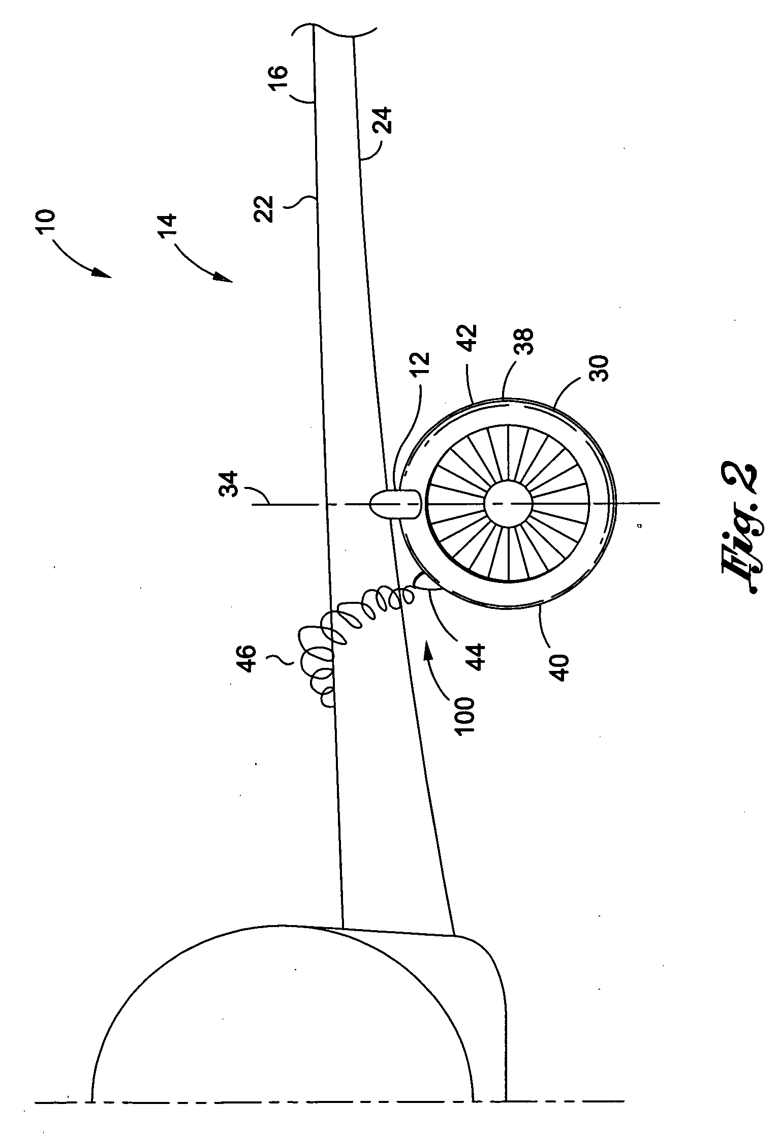
[0031]Referring now to the drawings wherein the showings are for purposes of illustrating preferred embodiments of the disclosure and not for purposes of limiting the same, shown in FIGS. 1 and 2 is a retractable chine assembly such as may be installed on a vehicle such as an aircraft 10. The aircraft 10 may have a wing assembly 14 including a wing 16 having a wing upper surface 22 and a wing lower surface 24. The retractable chine assembly may comprise at least one vortex generator or other aerodynamic device such as a chine 44 which is preferably hingedly mountable on an aircraft 10 such as on an engine nacelle 30 of the aircraft 10.

[0032]The chine 44 is preferably sized, configured, positioned and / or oriented on the engine nacelle 30 in order to generate a vortex 46 which preferably passes over a wing upper surface 22 of the wing 16 in order to interact with a nacelle wake 84 that may be generated by the nacelle at high angles of attack α. However, it is also contemplated that th...


PUM


Abstract

A retractable chine assembly includes at least one chine which is hingebly mountable to a surface such as of an aircraft having a wing. The chine is preferably configured to be movable between stowed and deployed positions. The aircraft may include an engine nacelle which may be mounted on an underside of the wing. The nacelle may generate a nacelle wake that passes over the wing upper surface at high angles of attack and induces flow separation. The chine is preferably configured such that a vortex generated thereby interacts which the nacelle wake to delay flow separation and stall.

Description

CROSS-REFERENCE TO RELATED APPLICATIONS[0001]Not ApplicableSTATEMENT RE: FEDERALLY SPONSORED RESEARCH / DEVELOPMENT[0002]Not ApplicableFIELD[0003]The present disclosure relates generally to aerodynamic control devices and, more particularly, to an aerodynamic device such as a chine assembly that may be configured to delay flow separation induced by a wake generated by an engine nacelle at high angles of attack.BACKGROUND[0004]On certain aircraft such as commercial airliners, tankers, airlifters and transport aircraft, aircraft engines are typically mounted in nacelles that extend from pylons under the wing. In many aircraft, the leading edge of the engine nacelle is positioned forward of the wing leading edge. At high angles of attack, the engine nacelle sheds a wake. For aircraft where the engine nacelles are spaced at a relatively large distance from the wing, the wake generated may pass underneath the wing.[0005]However, for installations where the engine nacelle is mounted in clos...

Claims


Application Information

Patent Timeline
Patent Type & Authority Applications(United States)
IPC IPC(8): B64C23/06
CPCB64C7/02Y02T50/162B64C23/06Y02T50/10
Inventor SCLAFANI, ANTHONY J.KONINGS, CHRISTOPHER A.
Owner THE BOEING CO
Why Eureka
Eureka Blog
Learn More