
System and apparatus for reducing the aerodynamic drag of a vehicle

Active Publication Date: 2018-01-18
STREAMLINERS INC
View PDF9 Cites 7 Cited by
  • Summary
  • Abstract
  • Description
  • Claims
  • Application Information

AI Technical Summary

Benefits of technology

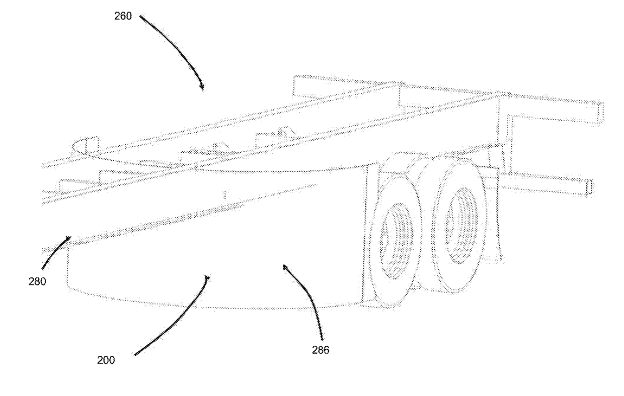
The present invention relates to an apparatus for reducing the aerodynamic drag of a vehicle, such as a semitrailer, intermodal chassis trailer, tanker truck or the like. The apparatus is designed to maintain a fixed position with respect to the rear tires of the vehicle, regardless of their position along the length of the vehicle. It is easy to install and has a minimum effect on the vehicle's weight or performance. The technical effects of the invention are to reduce the vehicle's fuel consumption and improve its efficiency.

Problems solved by technology

Even the mirrors, which are small relative to the overall vehicle size, contribute about 5% of the total drag of the vehicle, as their blunt shape is not aerodynamically efficient.
In addition, the rear tires of the trailer, also referred to as tandems, contribute significantly to the overall aerodynamic drag.
In particular, during vehicle travel, the airflow under the trailer strikes the rear tires at nearly full speed and results in significant aerodynamic drag on the vehicle.
The goal of such trailer skirts is to prevent airflow from entering the area under the trailer and impacting the rear tires, axles and brakes which, over the course of an average year of long haul driving, can be a significant contributor to fuel cost.
Notably, however, trailer skirts can be quite costly and can be somewhat complex to properly install, at least partially negating the annual fuel cost benefit achieved by their use.
In addition, commonly used skirts for standard semi-trailers are incompatible with intermodal chassis trailers and tankers due to the lack of a convenient place to mount the long, straight skirts.

Method used


Image

  • System and apparatus for reducing the aerodynamic drag of a vehicle
  • System and apparatus for reducing the aerodynamic drag of a vehicle
  • System and apparatus for reducing the aerodynamic drag of a vehicle

Examples


Embodiment Construction

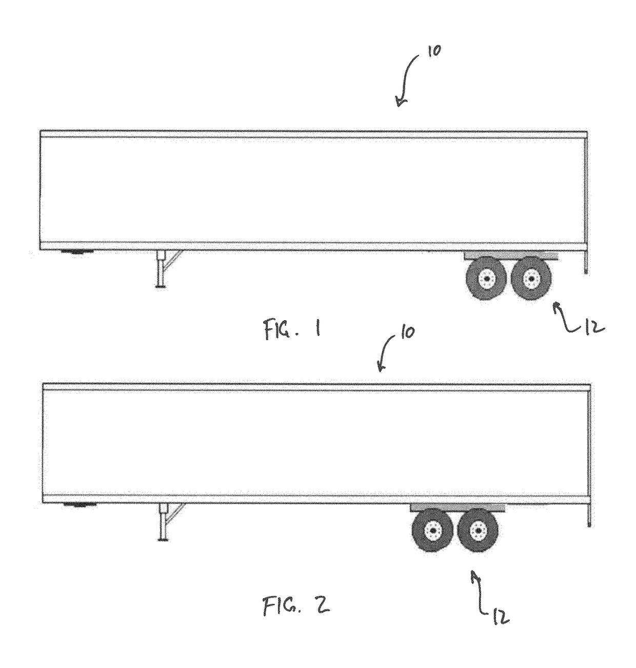
[0062]Referring first to FIGS. 1 and 2, a typical semi trailer 10 having rear tandems 12 with which the apparatus for reducing aerodynamic drag of the present invention is intended to be utilized, is shown. As is known in the art, the tandems 12 can be moved forward or aft on the trailer 10 based on weight and position of the cargo inside the trailer. For example, FIG. 1 shows the rear tandems 12 in a rear position, while FIG. 2 shows the rear tandems 12 and in a forward position.

[0063]Ignored for years, the rear tandems of semi trailers have been the recent focus of aerodynamic improvement attempts in the industry through the use of trailer skirts, which attempt to minimize or prevent airflow from entering the underside of the trailer to reduce aerodynamic drag on the rear tandems (or tires). One drawback, however, is that these skirts are very expensive to install and therefore are large costs to fleet owners and have associated long payback periods. In addition, depending on the ...


PUM


Abstract

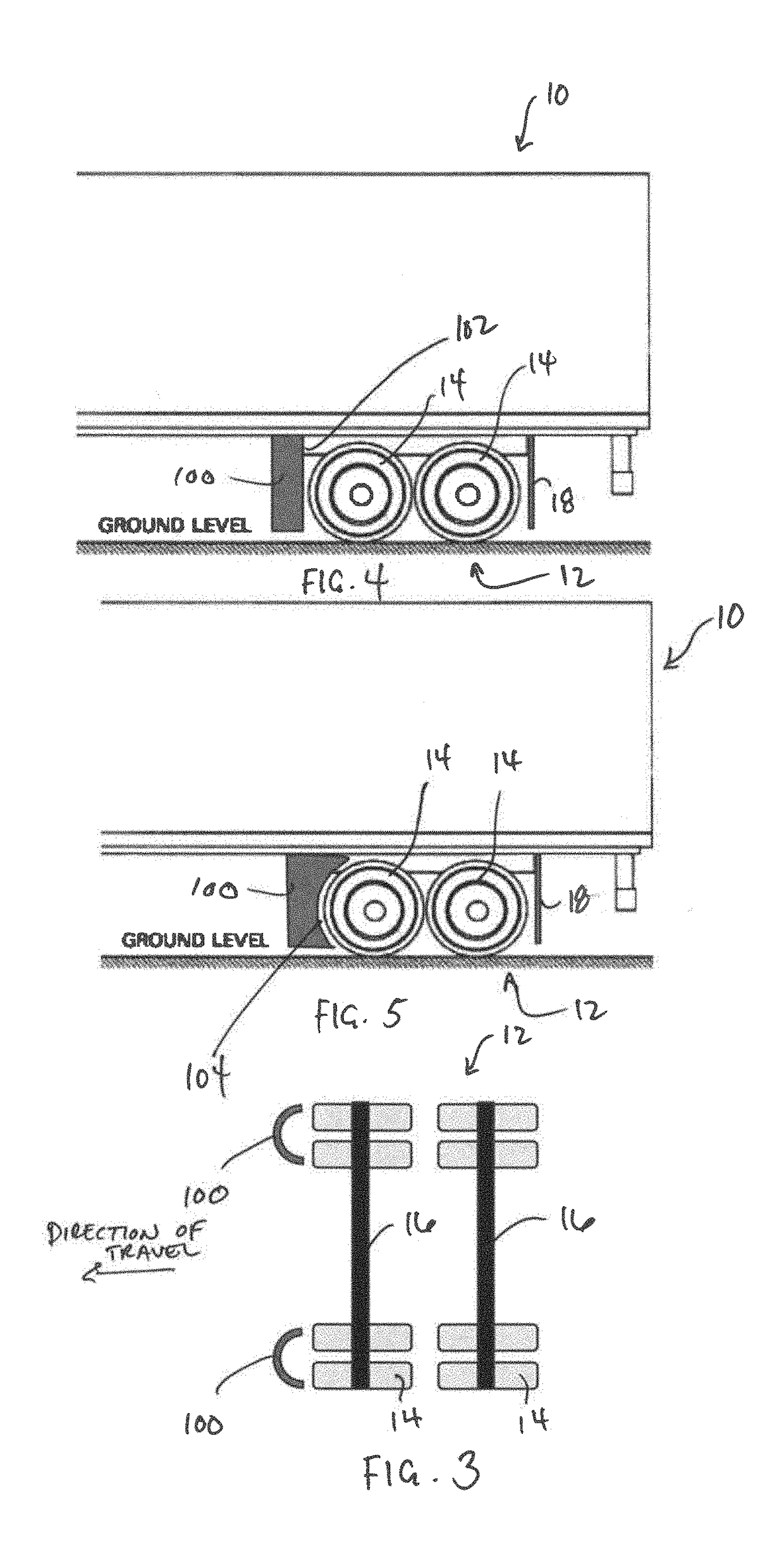
A vehicle includes a trailer, a tandem configured for attachment to the trailer, the tandem including at least a first axle having opposed left and right ends and at least one tire mounted to each of the left end and the right end, and a second axle rearward of the first axle and having opposed left and right ends and at least one tire mounted to each of the left end and the right end, and at least one forward air deflector mounted to the tandem forward of the tires of the first axle and being shaped so as to deflect air flow beneath the trailer laterally around the tires of the vehicle to reduce the aerodynamic drag of the vehicle.

Description

CROSS-REFERENCE TO RELATED APPLICATIONS[0001]This application claims the benefit of U.S. Provisional Application Ser. Nos. 62 / 363,689, filed on Jul. 18, 2016, and 62 / 506,000, filed on May 15, 2017, both of which are herein incorporated by reference in their entireties.FIELD OF THE INVENTION[0002]The present invention relates generally to an apparatus for reducing the aerodynamic drag of a vehicle and, more particularly, to an air deflector for directing air flow around drag-producing components, such as wheels, of a vehicle.BACKGROUND OF THE INVENTION[0003]There are millions of cars and trucks on the roads today, used for both personal passenger transport and the movement of goods, most of which rely on fossil fuel for propulsion. In the case of standard tractor trailers, at highway speeds, aerodynamic drag is responsible for approximately half of the vehicle's fuel burn, meaning that even slight reductions in aerodynamic drag can result in a significant improvement in fuel economy ...

Claims


Application Information

Patent Timeline
IPC IPC(8): B62D35/00B62D35/02
CPCB62D35/02B62D35/001Y02T10/88Y02T10/82
Inventor TONGUE, STEPHEN EDWARDHIMMELMANN, RICHARD ANDREWHAMM, JOSEPH R.
Owner STREAMLINERS INC
Learn More