Apparatus to improve the aerodynamics, fuel economy, docking and handling of heavy trucks

a technology for aerodynamics and airfoils, applied in the direction of roofs, transportation and packaging, vehicle arrangements, etc., can solve the problems of increasing weight, affecting and affecting the drag reduction effect of airfoils, so as to improve the aerodynamic effect of airfoils and reduce the effect of drag

Inactive Publication Date: 2010-07-06
DISTEL RICHARD HENRY +1
View PDF13 Cites 44 Cited by
  • Summary
  • Abstract
  • Description
  • Claims
  • Application Information

AI Technical Summary

Benefits of technology

[0043]The first embodiment of the invention employs preformed, specially shaped airfoils made of a semi-rigid, resilient material, positioned on or near the four outboard, corner edges of the aft face of the vehicle, attached with a plurality of hinges to the aft face of the vehicle, or to the aft faces of the doors of a vehicle having rear doors, utilizing the existing trailer door hinges and / or a plurality of hinges. The unhinged edges of the airfoils rest against and slide on the outer surface of the aft surface of the trailer or of the doors so that in the latter application, when the doors are swung 270 degrees from the closed position, contact between the trailer sides and the apex of the air foils causes the airfoils to flatten and self stow between the fully swung doors and the sides of the trailer. The airfoils are economically manufactured, easily installed and retrofitted and will deflect without damage if accidentally impacted. The purpose of the device is to reduce aerodynamic drag on the vehicle by simulating aft corner rounding of the trailer.
[0045]The third embodiment of the invention enhances the aerodynamic effect of the airfoils through the incorporation of specially designed, compact air nozzles that direct compressed air tangentially along the outer curvature of the airfoils to influence their drag reducing effect and / or contribute to vehicle stability. While reference is made to a heavy trailer, the invention can be applied to any box shaped vehicle having a bluff aft.

Problems solved by technology

While these airfoils may serve to reduce aerodynamic drag, they are large and rigid when deployed, making them subject to damage if accidentally contacted.
In addition the plurality of parts and interconnections, and multiple fastening points make them costly to manufacture and install.
Even if constructed, as suggested, of aluminum, they add considerable weight and the scrap value of this material makes them targets of theft.
In either case this device is not suitable for application to heavy trailers due to door function and loading requirements, and is not retrofittable.
It is questionable whether this is a proper application of the Coanda effect.
Although the devices move forward so as to not project behind the aft end of the trailer, there is no provision to allow the doors to be swung flush to the sides of the trailer.
In the deployed orientation, the vanes and brackets extend aft of the end of the trailer making them susceptible to accidental damage from rear or side impact.
Due to these features, the self-stowing aspect of the devices is impractical and requires high cost to manufacture, install and maintain.
This makes them subject to damage or dislodgement and reduces their real world practicality.
The devices described in and extend rigidly straight back from the aft of the trailer making them susceptible to accidental damage from rear or side impact.
The plurality of parts increases the cost, weight and difficulty of installation.
This makes the devices susceptible to damage from accidental side or rear impact.
Even this reduced length does not alleviate the potential for accidental damage.

Method used


Image

  • Apparatus to improve the aerodynamics, fuel economy, docking and handling of heavy trucks
  • Apparatus to improve the aerodynamics, fuel economy, docking and handling of heavy trucks
  • Apparatus to improve the aerodynamics, fuel economy, docking and handling of heavy trucks

Examples


first embodiment

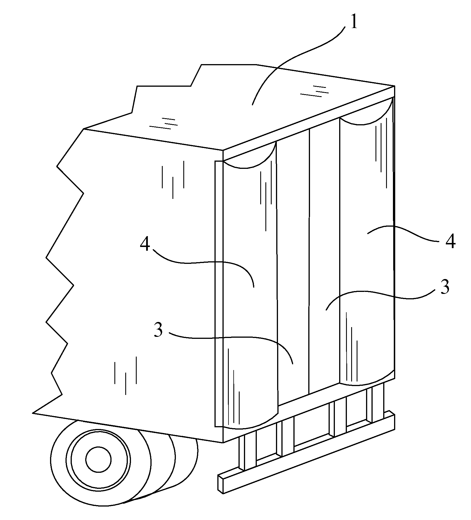
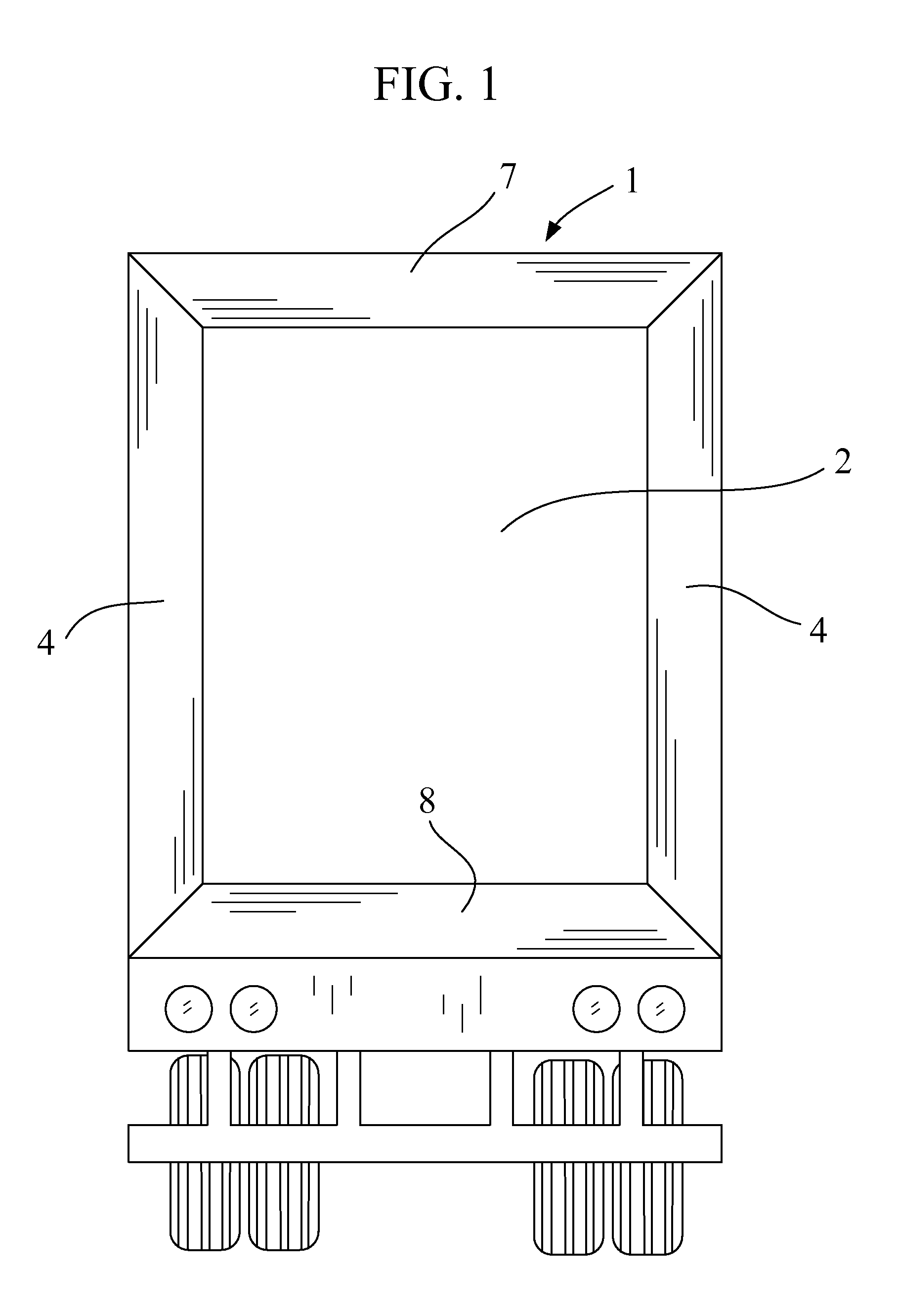
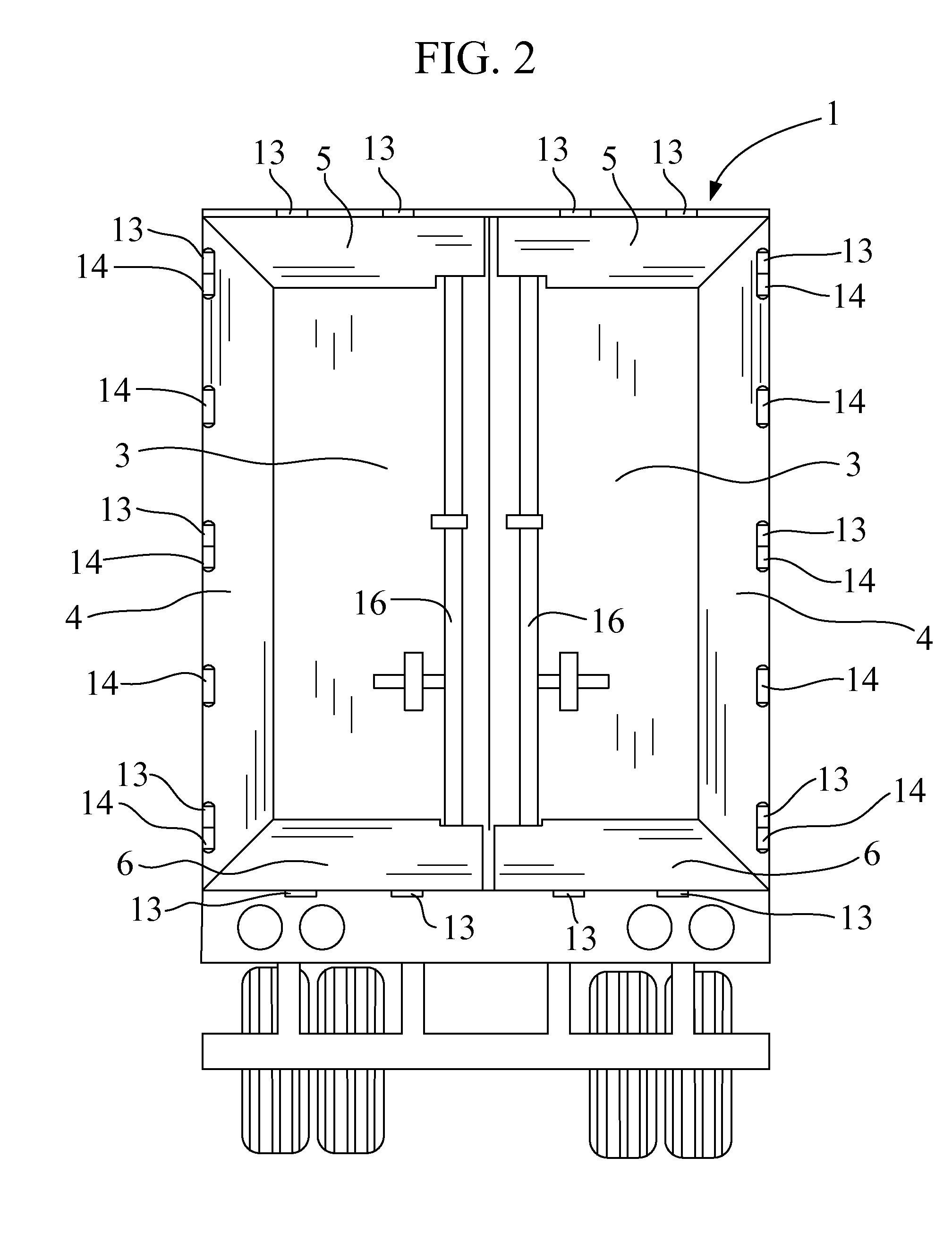
[0063]the invention applies either, as shown in FIG. 1, to a vehicle 1 without rear doors, and then consists of a set of symmetrically opposite airfoils 4, 7 and 8, designed and located on the aft flat surface 2 of a vehicle, to be close to the four aft edge corners so as to create a contiguous surface with the exterior sides of the vehicle; or, as shown in FIG. 2, to a vehicle 1 having two rear swinging doors 3, and then consists of a set of symmetrically opposite airfoils 4, 5 and 6, designed and located on the aft flat surfaces of the rear doors of the vehicle, to be as close to the four aft edge corners so as to create a contiguous surface with the exterior edges of the doors and the sides of the vehicle; essentially adjacent to the full perimeter of the aft face.

[0064]As shown in FIG. 2, due to their attachment to the two aft doors, the top and bottom airfoils 5 and 6 are shorter but generally similar in form and design to the top and bottom airfoils 7 and 8, shown in FIG. 1, a...

second embodiment

[0073]the invention (one application of which is shown in FIG. 3, side airfoils 4 used alone) consists of the selective attachment of airfoils to less than all four, edge corners of the vehicle, so that the top, bottom and side airfoils may be employed independently or in various combinations.

third embodiment

[0074]the invention, shown in FIGS. 10 and 11, consists of the addition of a plurality of air nozzles 11 to any or all of the airfoils 4, 5, 6, 7 and 8, designed to direct blown air tangentially along the outer surface of the airfoils. The nozzles are positioned in slots cut or formed in the faces of the airfoils, as close as possible to the attachment edge.

[0075]The nozzles 11 are made of a weather resistant material such as plastic, stainless steel or anodized aluminum, designed to be cast, fabricated or molded in a compact shape so as to not interfere with airfoil stowing and to be economically manufactured. The nozzle design incorporates a “tee” or “ell” shaped fitting for attachment of air supply tubing.

[0076]The design of all embodiments of the invention is such that installation, adaptation and replacement can be quickly accomplished in the field using hand tools, or can be a part of the original vehicle manufacturing process with little added labor. It is intended that, to s...


PUM


Abstract

A device to alter and / or reduce the aerodynamic, base drag on and improve the stability of a bluff bodied vehicle, such as a heavy trailer with or without two aft vertically hinged doors, comprised of preformed, resilient, semi-circular airfoils permanently attached with hinges to the aft planar surface or the rear doors of the vehicle, at the vertical left and right corner edges, the horizontal top corner edge, the horizontal bottom corner edge of the vehicle, or at two or more of these positions. The airfoils self stow when the doors are opened and resume their initial shape when the doors are closed. If accidentally impacted, the airfoils deflect and then resume their initial shape. The airfoils can be fitted with compact air nozzles to blow air tangentially over their outer surfaces to enhance their effect. The device is inexpensive, lightweight and easily installed, replaced and retrofitted.

Description

CROSS REFERENCE TO RELATED APPLICATIONS[0001]This application does not claim the benefit of any prior filed non-provisional applications.GOVERNMENT INTERESTS[0002]The invention described herein was developed solely by the applicants with no financial or other assistance from the United States government.REFERENCE TO COMPACT DISC APPENDIX[0003]Not applicable.BACKGROUND[0004]1. Area of Invention[0005]The invention is a device, capable of self-stowing, to improve the aerodynamics and / or reduce base drag at the aft end of bluff bodies, such as box shaped heavy trailers towed by powered tractor trucks and similarly shaped cargo and passenger vehicles, that does not impede trailer docking and is capable of incorporating air blowing techniques.[0006]2. Essential Perameters[0007]The purpose of the invention is to improve of the aerodynamics at the aft end of a heavy trailer or other vehicle having a bluff body to reduce aerodynamic drag. The reduction of drag lessens the energy required fro...

Claims


Application Information

Patent Timeline
Patent Type & Authority Patents(United States)
IPC IPC(8): B62D35/00
CPCB62D35/001
Inventor DISTEL, RICHARD HENRYDISTEL, RICHARD ALBERT
Owner DISTEL RICHARD HENRY
Why Eureka
Try Eureka