Front end structure of vehicle

a technology for front end structures and vehicles, applied in the direction of superstructure subunits, vehicle components, propulsion parts, etc., can solve the problems of heat exchangers dropping in cooling ability, air running through heat exchangers being decreased, and heat exchangers falling in cooling ability, so as to achieve the effect of improving cooling ability

Inactive Publication Date: 2008-11-18
DENSO CORP
View PDF17 Cites 48 Cited by
  • Summary
  • Abstract
  • Description
  • Claims
  • Application Information

AI Technical Summary

Benefits of technology

[0007]An object of the present invention, in consideration of the above point, is to provide a front end structure of a vehicle surrounding heat exchangers with ducts so as to improve the cooling ability of the heat exchangers.
[0009]Due to this, when the vehicle is at rest and when being driven at a low speed, the air resistance can be reduced, so the cooling air running through the heat exchangers (1, 2) can be increased and the heat exchangers (1, 2) can be improved in cooling ability. Further, when there is no cover (9) at the vehicle bottom side, when driven at a high speed, fresh air flows in through the first through holes (13a), so the cooling air running through the heat exchangers (1, 2) can be increased and the heat exchangers (1, 2) can be improved in cooling ability. Therefore, in the entire vehicle speed region, the heat exchangers (1, 2) can be improved in cooling ability.
[0011]Due to this, even when the vehicle bottom side is provided with a cover (9), effects similar to those of the above can be obtained.
[0013]Due to this, hot air can be prevented from reaching to the front end sides of the heat exchangers (1, 2), so the heat exchangers (1, 2) can be further improved in cooling ability. Further, preferably, the first through holes (13a) are arranged at the vehicle rear side of the reinforced bumper (7). Due to this, the passage for inflow of fresh air can be secured. Incidentally, the reference numerals in parentheses after the above means are examples showing the correspondence with the specific means described in the later explained embodiment.

Problems solved by technology

The radiator, condenser, and heat exchangers mounted in a vehicle use air introduced from the vehicle front end side to cool cooling water, a refrigerant, or other fluid, but there is the problem that when the vehicle is at rest or when the vehicle speed is low, the hot air in the engine compartment heated by the engine ends up reaching the front end sides of the heat exchangers (vehicle) causing the heat exchangers to fall in cooling ability.
Therefore, the problem arises that when the vehicle is at rest and when the vehicle speed is low, the cooling air running through the heat exchanger is decreased causing the heat exchangers to drop in cooling ability.

Method used


Image

  • Front end structure of vehicle
  • Front end structure of vehicle
  • Front end structure of vehicle

Examples


first embodiment

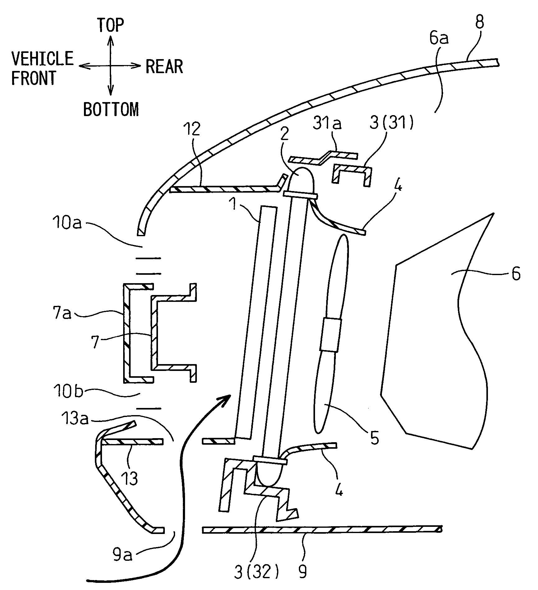
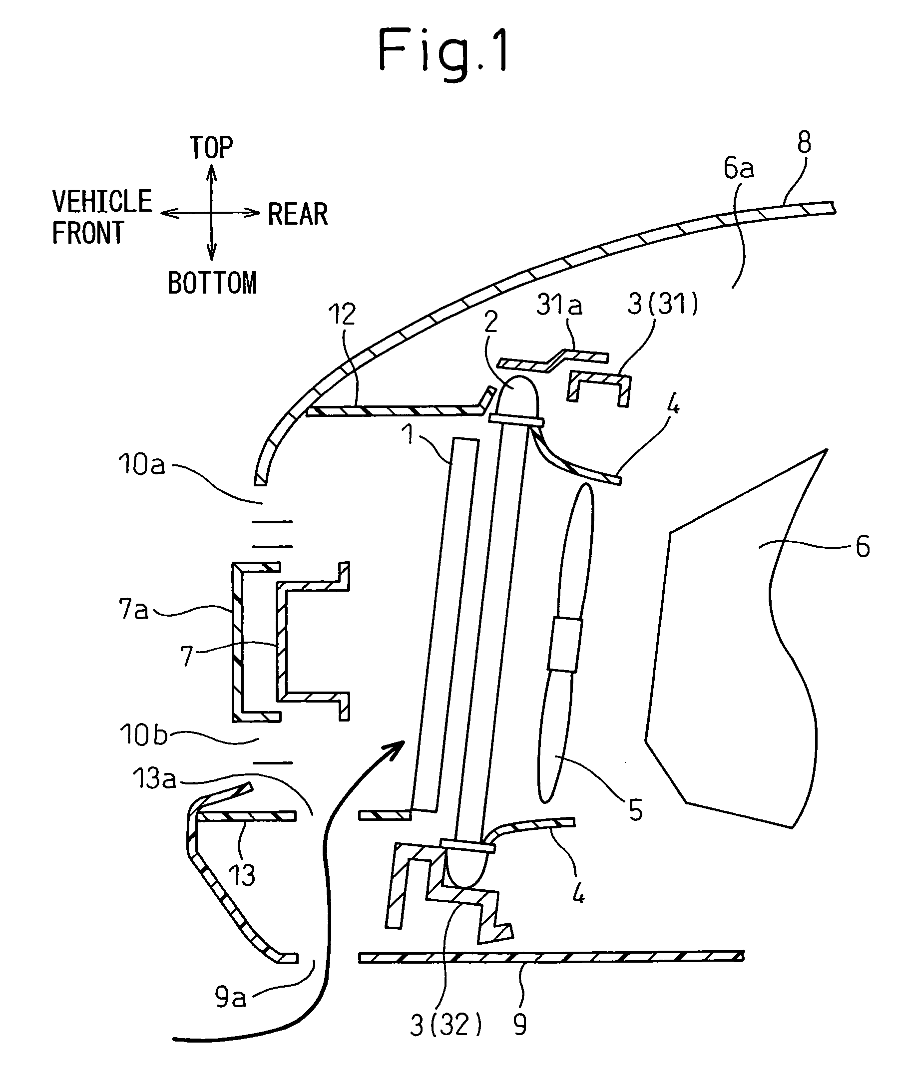
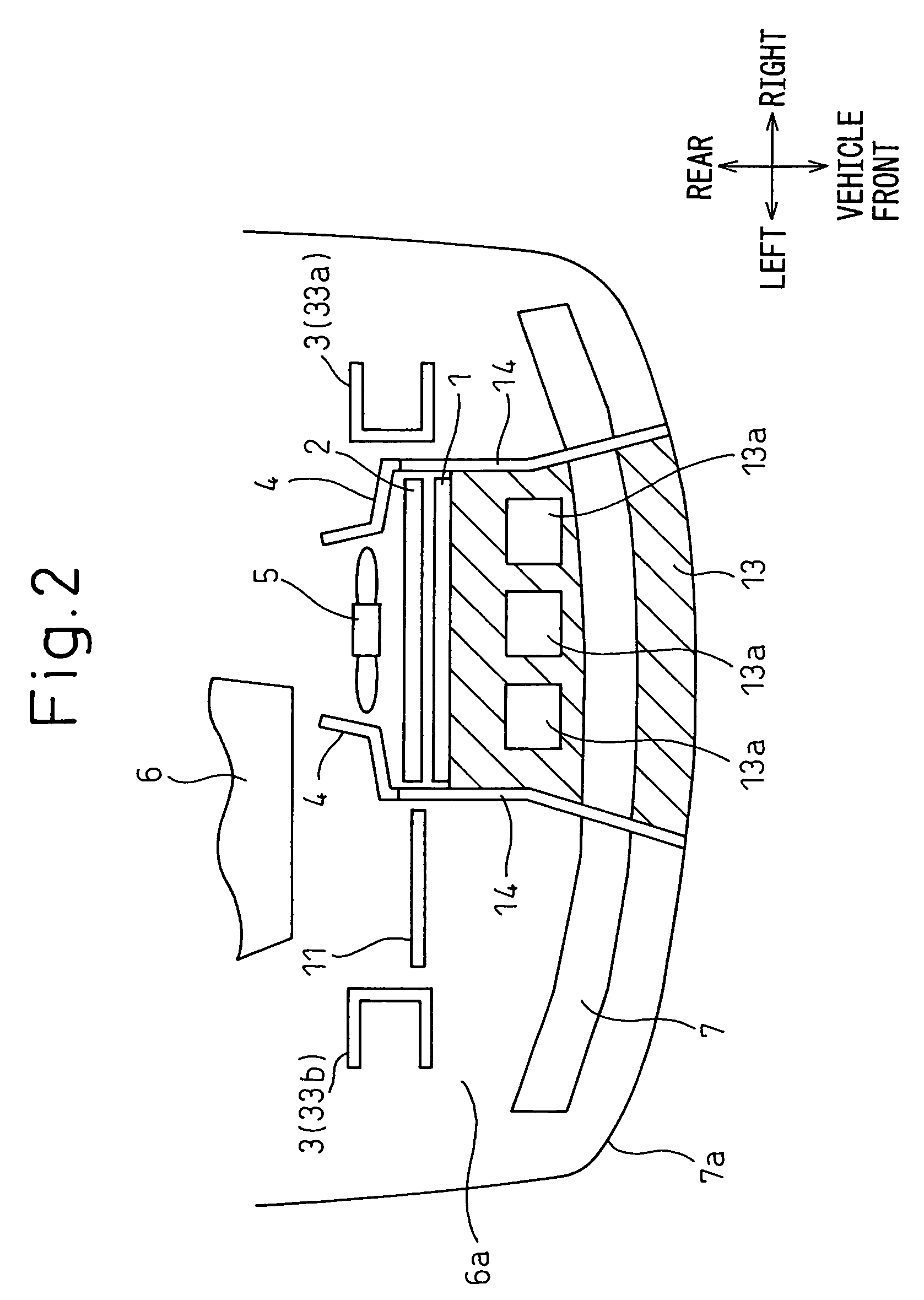
[0018]Below, a first embodiment of the present invention will be explained with reference to FIG. 1 and FIG. 2. FIG. 1 is a cross-sectional view of a front end structure of a vehicle according to the first embodiment.

[0019]As shown in FIG. 1, a condenser 1 and a radiator 2 of the first embodiment are mounted at a chassis through a common carrier 3. The condenser 1 is placed at the upstream-most part of the carrier 3 (frontmost part), while the radiator 2 is placed at the downstream side of the condenser 1. Further, a blower 5 is provided at the downstream side of the radiator 2. Note that the condenser 1 and the radiator 2 will also be referred to together as “the heat exchangers 1, 2”.

[0020]The condenser 1 is a heat exchanger exchanging heat between a refrigerant circulating through a refrigeration cycle (not shown) and the outside air so as to cool the refrigerant. Further, the radiator 2 is a heat exchanger exchanging heat between engine cooling water and outside air to cool the ...

second embodiment

[0034]Next, a second embodiment of the present invention will be explained based on FIG. 3. Parts the same as in the above first embodiment are assigned the same reference numerals and explanations therefore are omitted. FIG. 3 is a cross-sectional view of the front end structure of a vehicle according to the second embodiment.

[0035]In the configuration of the above first embodiment, when the vehicle is at rest and when being driven at a low speed, hot air in the engine compartment 6a was liable to pass between the clearance of the bottom side beam member 32 of the carrier 3 and the cover 9 to reach the front end sides of the heat exchangers 1, 2 and thereby cause the heat exchangers 1, 2 to drop in cooling ability.

[0036]As opposed to this, in the second embodiment, as shown in FIG. 3, a closed surrounding member 15 connecting the first through holes 13a and the corresponding second through holes 9a is provided between the bottom duct 13 and the cover 9. One opening of the closed su...


PUM


Abstract

A front end structure of a vehicle surrounding heat exchangers with ducts to thereby improve the heat exchangers in cooling ability, that is, a front end structure of a vehicle provided with heat exchangers positioned in an engine compartment in which an engine is mounted and exchanging heat between air and a heat medium, wherein the heat exchangers are surrounded by duct members sticking out to the vehicle front side, preventing hot air in the engine compartment from reaching the front end sides of the heat exchangers, and guiding air present at the vehicle front side to the heat exchangers and wherein among the duct members, a bottom duct positioned at the vehicle bottom side is formed with first through holes running through the vehicle in the up-down direction.

Description

BACKGROUND OF THE INVENTION[0001]1. Field of the Invention[0002]The present invention relates to the front end structure of a vehicle forming the front end of the chassis of the vehicle.[0003]2. Description of the Related Art[0004]The radiator, condenser, and heat exchangers mounted in a vehicle use air introduced from the vehicle front end side to cool cooling water, a refrigerant, or other fluid, but there is the problem that when the vehicle is at rest or when the vehicle speed is low, the hot air in the engine compartment heated by the engine ends up reaching the front end sides of the heat exchangers (vehicle) causing the heat exchangers to fall in cooling ability.[0005]To deal with this problem, the method has been proposed of surrounding the heat exchangers (at the top, bottom, left, and right) with ducts sticking out to the vehicle front side so as to prevent hot air from reaching the heat exchangers. Due to this, when the vehicle speed is high, the running air is effectivel...

Claims


Application Information

Patent Timeline
Patent Type & Authority Patents(United States)
IPC IPC(8): B60K11/00B60K13/02
CPCB60K11/04B60K11/08B62D25/084
Inventor KUNIKATA, YUHEI
Owner DENSO CORP
Why Eureka
Try Eureka