Device for reducing vehicle aerodynamic resistance

a technology for reducing vehicle aerodynamic resistance, which is applied in the direction of roofs, transportation and packaging, vehicle arrangements, etc., can solve the problems of reducing the aerodynamic resistance of the vehicle when moving, and achieve the effect of reducing the aerodynamic resistance of the vehicl

Active Publication Date: 2012-05-29
FREIGHT WING
View PDF31 Cites 43 Cited by
  • Summary
  • Abstract
  • Description
  • Claims
  • Application Information

AI Technical Summary

Benefits of technology

[0006]In general, a device for reducing vehicle aerodynamic resistance disposed on the bottom of a vehicle having a generally rectangular body disposed above rear wheels, when made in accordance with this invention, comprises a single or plurality of opposing flexible flat sheets attached to the underside of the rectangular body, each having a top edge disposed adjacent the bottom of the rectangular body and a bottom edge disposed to a predetermined height above the ground such that the opposing sheets may either be parallel to the sides of the rectangular body or angled inward such that the leading edge of the opposing sheets are closer together towards the front of the rectangular body and disposed in an angled orientation to the centerline of the vehicle. A plurality of attachment brackets having a hinged degree of freedom whose axis is in line with the top edge of the opposed sheets connect the upper edge of the opposed sheets to the underside of the rectangular body. A plurality of load bearing flexible struts of a predetermined size and flexibility attached to the bottom of the rectangular body a predetermined distance from the inside of the opposed sheets and attached to the opposed sheets at a predetermined distance from the bottom edge of the opposed sheets, having a hinged degree of freedom at both the underside of the rectangular body and at the opposed sheet attachment, which can absorb impact in the event of a lateral or vertical impact, whereby the flexible load bearing struts and flexible opposed sheets bend toward the rectangular body in an elastic manner and allow the opposed sheets to return undamaged to a planar geometry upon ending the application of the external force used to create the bending. The presence of the opposed sheets direct the airflow around the rear wheels and axle components to reduce the aerodynamic resistance of the vehicle when moving.

Problems solved by technology

The presence of the opposed sheets direct the airflow around the rear wheels and axle components to reduce the aerodynamic resistance of the vehicle when moving.

Method used


Image

  • Device for reducing vehicle aerodynamic resistance
  • Device for reducing vehicle aerodynamic resistance
  • Device for reducing vehicle aerodynamic resistance

Examples


Embodiment Construction

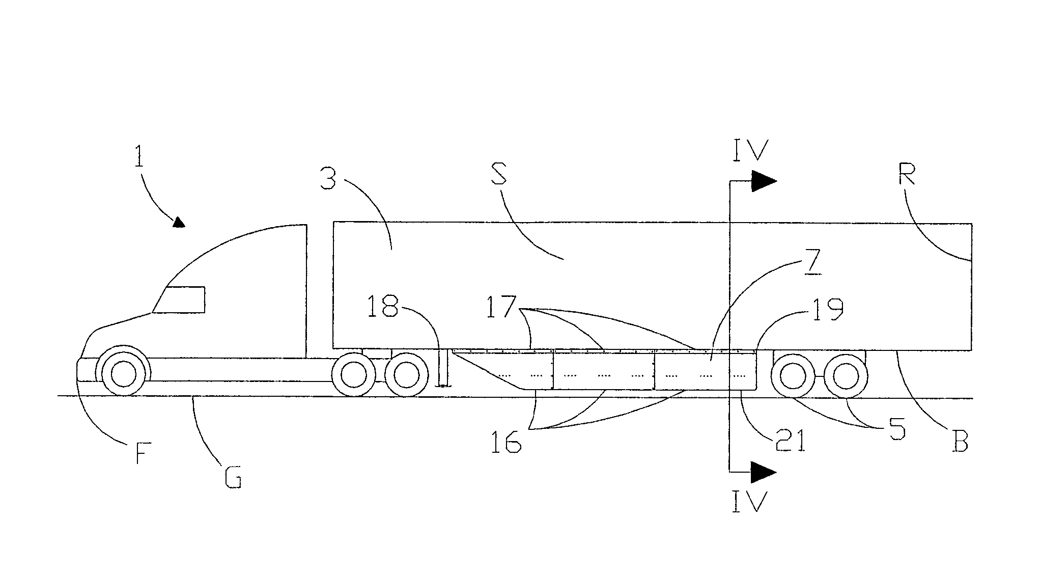
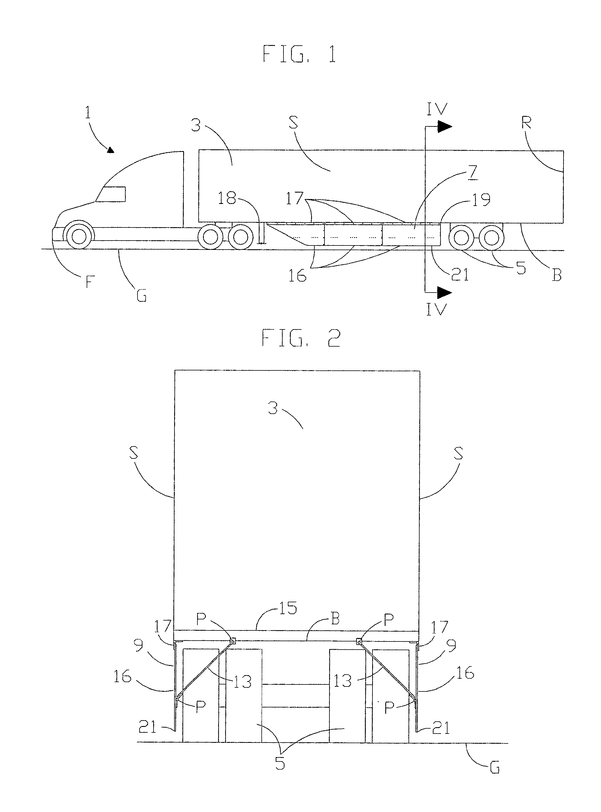
[0017]Referring now to the drawings in detail and in particular to FIGS. 1, 2 and 3, there is shown a vehicle 1 such as a trailer truck, having a generally rectangular body 3 having a front F, rear R, bottom B and opposed sides S mounted above rear wheels 5 and a device 7 for reducing the aerodynamic resistance of the vehicle 1 when it moves.

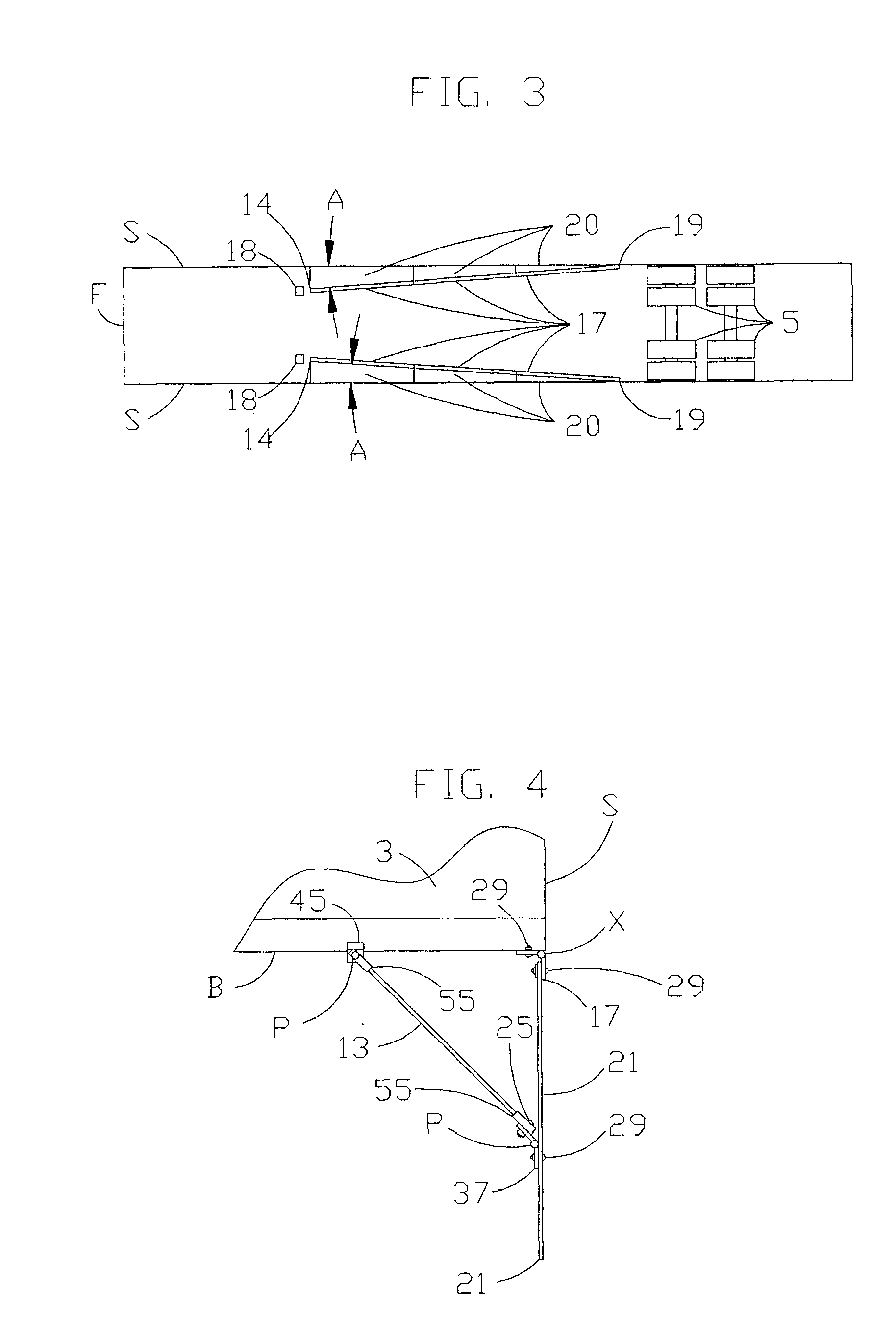
[0018]The device 7 comprises a pair of opposed airfoils 9 disposed beneath the rectangular body 3. Each opposing airfoil comprises opposed load bearing members 17 of a predetermined size, which are attached continuously and linearly to the bottom B of the rectangular body 3, and define the position of the opposed airfoils 9 on the vehicle 1. As shown in the bottom view of FIG. 3, the opposed load bearing members 17 form opposed acute mounting angles A with the sides S of the rectangular body 3. The acute mounting angles A are disposed at rearward mounting points 19 adjacent the sides S of the rectangular body at a predetermined distance in front...


PUM


Abstract

A device for reducing vehicle aerodynamic resistance for vehicles having a generally rectangular body disposed above rear wheels, comprising a plurality of flexible opposing flat sheets and a plurality flexible load bearing struts attached to the bottom of the rectangular body, that bend to resist damage when struck by the ground, and guide airflow around the rear wheels of the vehicle to reduce its aerodynamic resistance when moving.

Description

TECHNICAL FIELD[0001]The invention relates to a device for reducing the aerodynamic resistance of a moving, rectangular shaped vehicle and more particularly to a pair of opposing airfoils that are mounted underneath the vehicle adjacent its sides.BACKGROUND ART[0002]It is well known that streamlining the undercarriage of a long vehicle such as a trailer truck or straight van truck will reduce the aerodynamic resistance of a moving vehicle and thus save fuel. However, streamlining the undercarriage of a long vehicle such as a semi-trailer is impractical because integrated enclosures are heavy, costly, easily damaged, interfere with standardized structural design, and prevent access to parts and equipment underneath the vehicle. Consequently, removable attachments have been designed to streamline the undercarriage of long vehicles. However, past designs for removable attachments have not achieved significant utilization because they are typically easily damaged, difficult to repair, d...

Claims


Application Information

Patent Timeline
Patent Type & Authority Patents(United States)
IPC IPC(8): B62D35/02
CPCB62D35/001B62D35/02Y10S180/903Y02T10/82Y02T10/88
Inventor GRAHAM, SEAN CGRAHAM, MIKEHOLLIFIELD, COTY T
Owner FREIGHT WING
Why Eureka
Try Eureka