

Vehicle wheel assembly including a self-deployed wheel shutter system
a technology of vehicle wheel and shutter system, which is applied in the direction of vehicle components, wheel protection, transportation and packaging, etc., can solve the problems of increasing aerodynamic drag and adversely affecting fuel economy
- Summary
- Abstract
- Description
- Claims
- Application Information
AI Technical Summary
Benefits of technology
Problems solved by technology
Method used
Image

Examples
Embodiment Construction
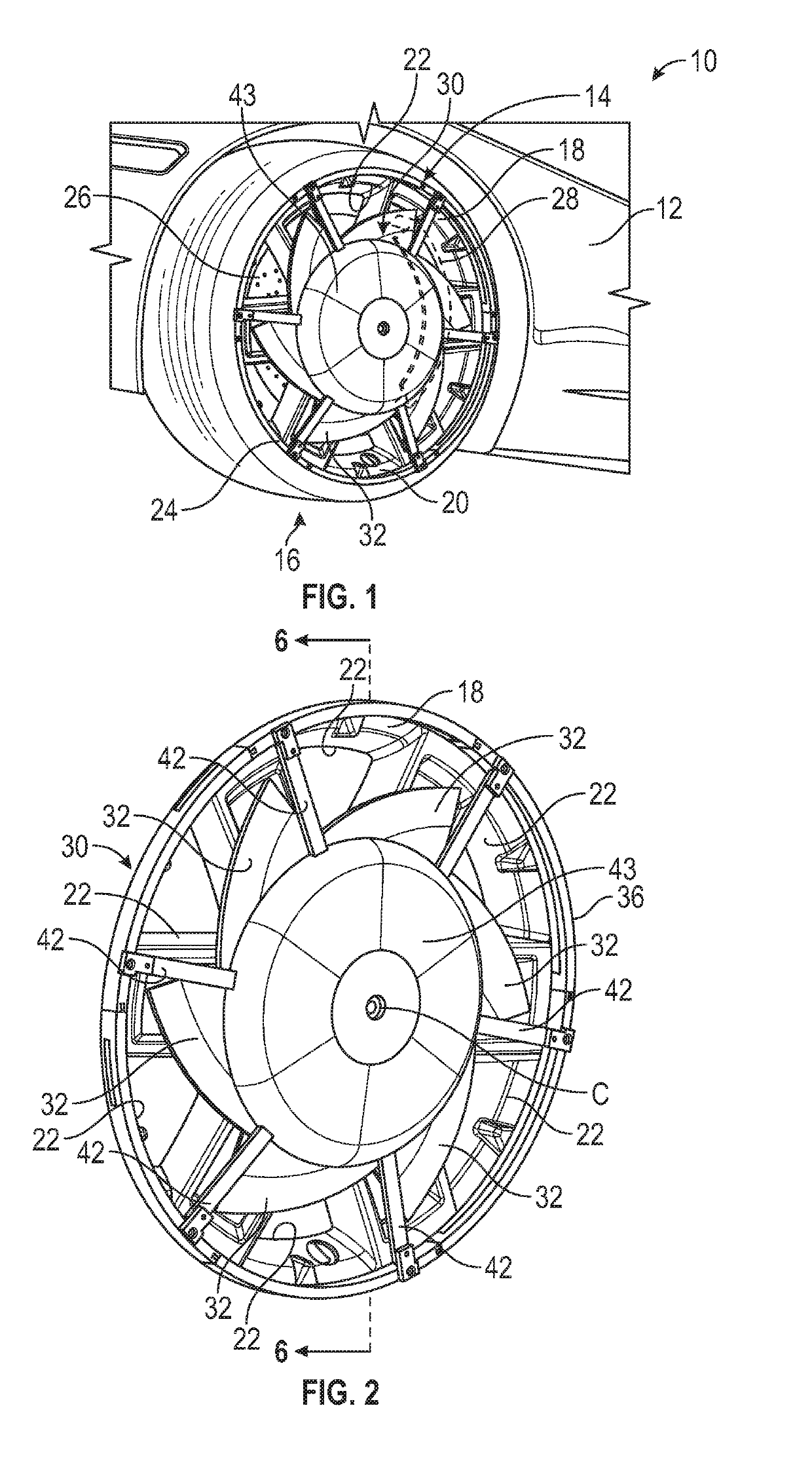
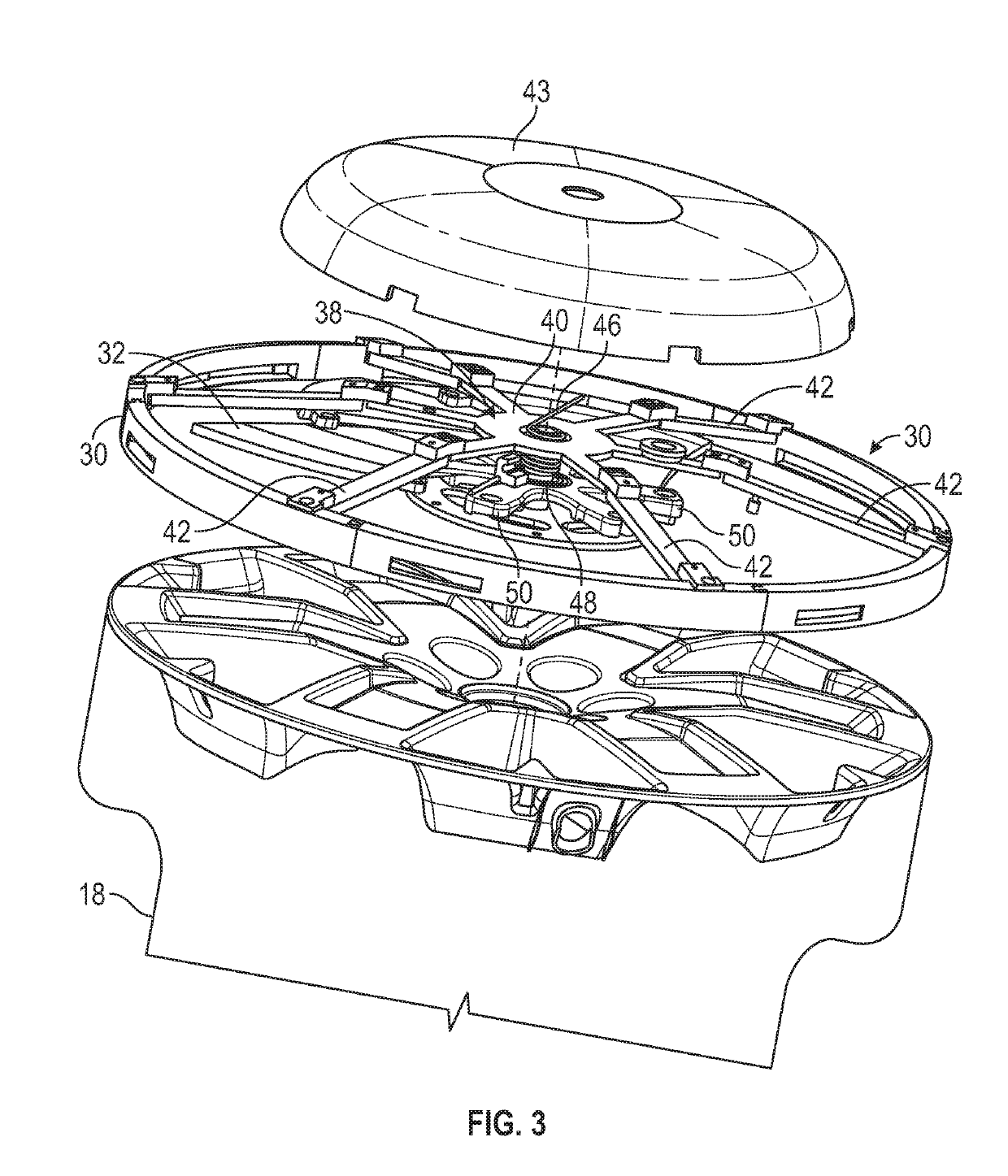
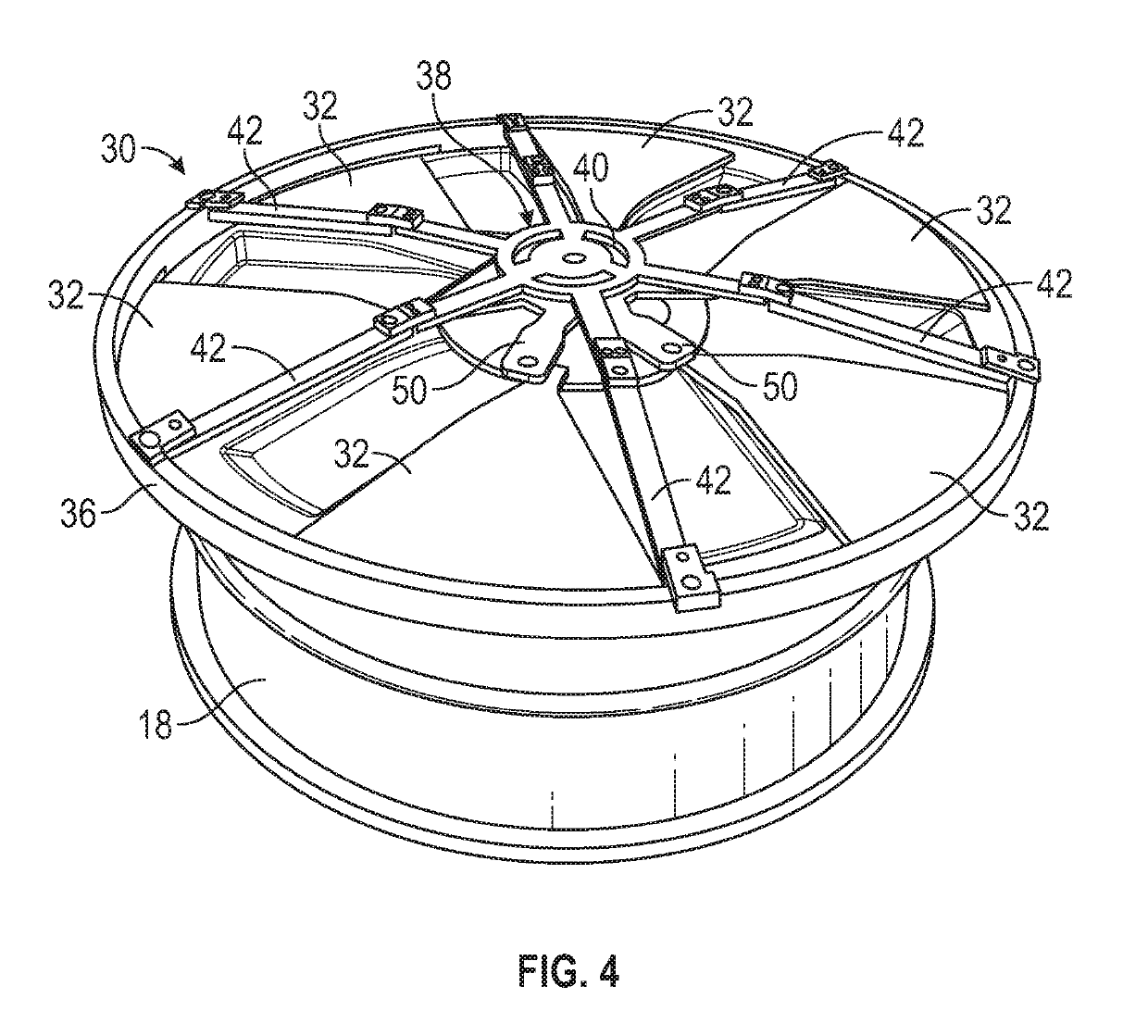
[0022]Referring to the drawings, wherein like reference numbers correspond to like or similar components throughout the several figures, and beginning with FIG. 1, a vehicle 10 (e.g., a car) includes a vehicle body 12, a vehicle wheel assembly 14 coupled to the vehicle body 12, and a tire 16 coupled to the vehicle wheel assembly 14. The vehicle wheel assembly 14 includes a vehicle wheel 18 coupled to the tire 16. Therefore, the vehicle wheel 18 supports the tire 16. The vehicle wheel 18 includes a wheel body 20 and has a plurality of openings 22 (e.g., thru-holes) extending completely through the wheel body 20. The vehicle 10 includes a brake assembly 24 coupled to the vehicle wheel 18. The brake assembly 24 is configured to decelerate the vehicle 10 and at least includes a brake rotor 26 and a brake shoe 28 movably coupled to the brake rotor 26. The openings 22 extend completely through the wheel body 20 to allow air to flow through the vehicle wheel 18 and into the brake assembly ...
PUM
 Abstract
Description
Claims
Application Information