Mounting Device and Method for Visual Communication

a technology for mounting devices and visual communications, applied in the direction of mobile visual advertising, instruments, signs, etc., can solve problems such as compromising the integrity of the device, unforeseen and unfortunate damage or inconvenience, etc., to reduce or eliminate potential clearance issues, reduce aerodynamic drag, and increase visual appeal

Active Publication Date: 2016-07-21
GEORGIADIS FRANCOIS
View PDF32 Cites 5 Cited by
  • Summary
  • Abstract
  • Description
  • Claims
  • Application Information

AI Technical Summary

Benefits of technology

[0008]The present invention is directed to a method of communication that can be tailored to the individual user. It provides the ability for the user to individually select and modify messages, logos, advertisement, public service announcements or indicia. The method incorporates a device comprising a frame with panels either continuously connected or attachably and removeably mounted to the frame in a streamlined fashion in order to increase visual appeal, minimize aerodynamic drag, and reduce or eliminate potential clearance issues. It utilizes the existing front or rear space of a vehicle, and in a preferred embodiment is mounted within the license plate recess, thereby reducing force on the device from airflow around the vehicle. This placement also renders the device less obstructed and reduces potential vulnerability to environmental elements relative to currently available designs. Utilization of the device within the license plate recess also improves energy efficiency and reduces wear on the surfaces used for visual communication by minimizing or avoiding high speed impacts of small objects, such as but not limited to road debris and insects.
[0009]The device and method described also avoids potential operating issues inherently imposed on vehicle operation due to currently existing methodologies. Typical examples of current methodologies involve upright, often triangular surfaces, which are mounted vertically with respect to the plane of the road and placed on the highest surface of a vehicle. In certain circumstances, current methodologies increase the effective height of a vehicle, causing potentially unforeseen and unfortunate damage or inconvenience. This can occur particularly in scenarios which are adversely affected by adding to vehicle height, such as with placement on a truck driven through a zone with height restrictions, including but not limited to small tunnels or bridges, or when being loaded for shipping. Damage to the present invention would, in most cases, require a much more localized and violent event to compromise the integrity of the device.
[0010]The present invention is also superior to methodologies involving communications utilizing the surface of rear or side facing glass, as these methodologies potentially limit and obscure the visual field of the operator. It also provides advantages over methodologies involving affixing indicia to a bumper, such as bumper stickers or magnets, in that it is higher in the visual field of observers, and less susceptible to damage. Furthermore, positioning of the invention around the license plate within the recess protects it from visual obstruction.
[0011]Another meaningful benefit of this device and method involves taking advantage of common regulations regarding existing vehicle identification mounting. In virtually all instances, governing bodies, at minimum, require placement of identification information unique to each vehicle to the rear and in plain view. Such requirements and the desire to prevent possible theft or misuse of said identifying information have led vehicle manufacturers to provide rather robust “hard points” on which to mount such identification. No such comparable points are commonly located in positions where current methodologies are typically placed. In utilizing this mounting solution, an element of security and reliability is introduced.

Problems solved by technology

In certain circumstances, current methodologies increase the effective height of a vehicle, causing potentially unforeseen and unfortunate damage or inconvenience.
This can occur particularly in scenarios which are adversely affected by adding to vehicle height, such as with placement on a truck driven through a zone with height restrictions, including but not limited to small tunnels or bridges, or when being loaded for shipping.
Damage to the present invention would, in most cases, require a much more localized and violent event to compromise the integrity of the device.

Method used


Image

  • Mounting Device and Method for Visual Communication
  • Mounting Device and Method for Visual Communication
  • Mounting Device and Method for Visual Communication

Examples


Embodiment Construction

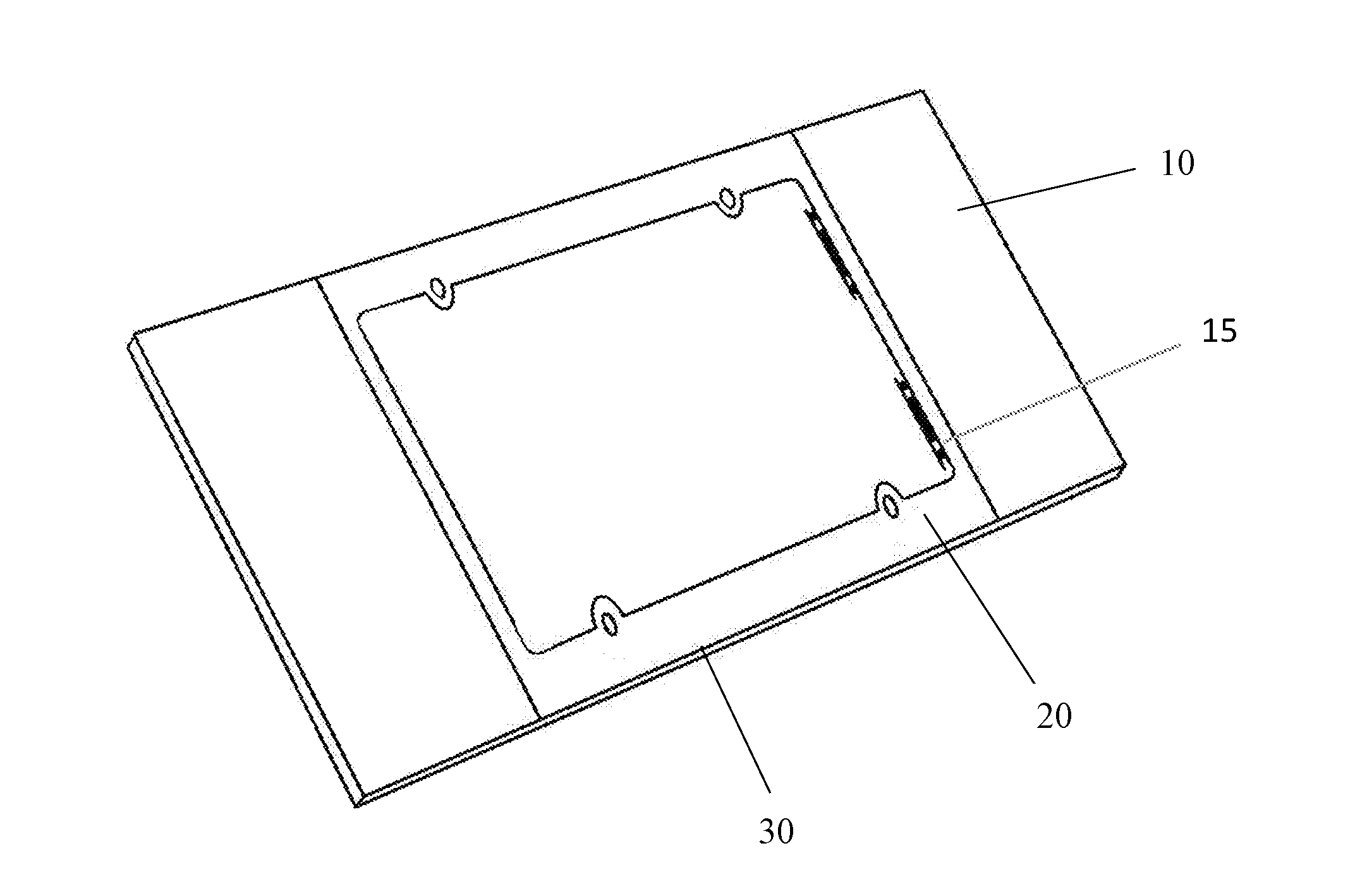
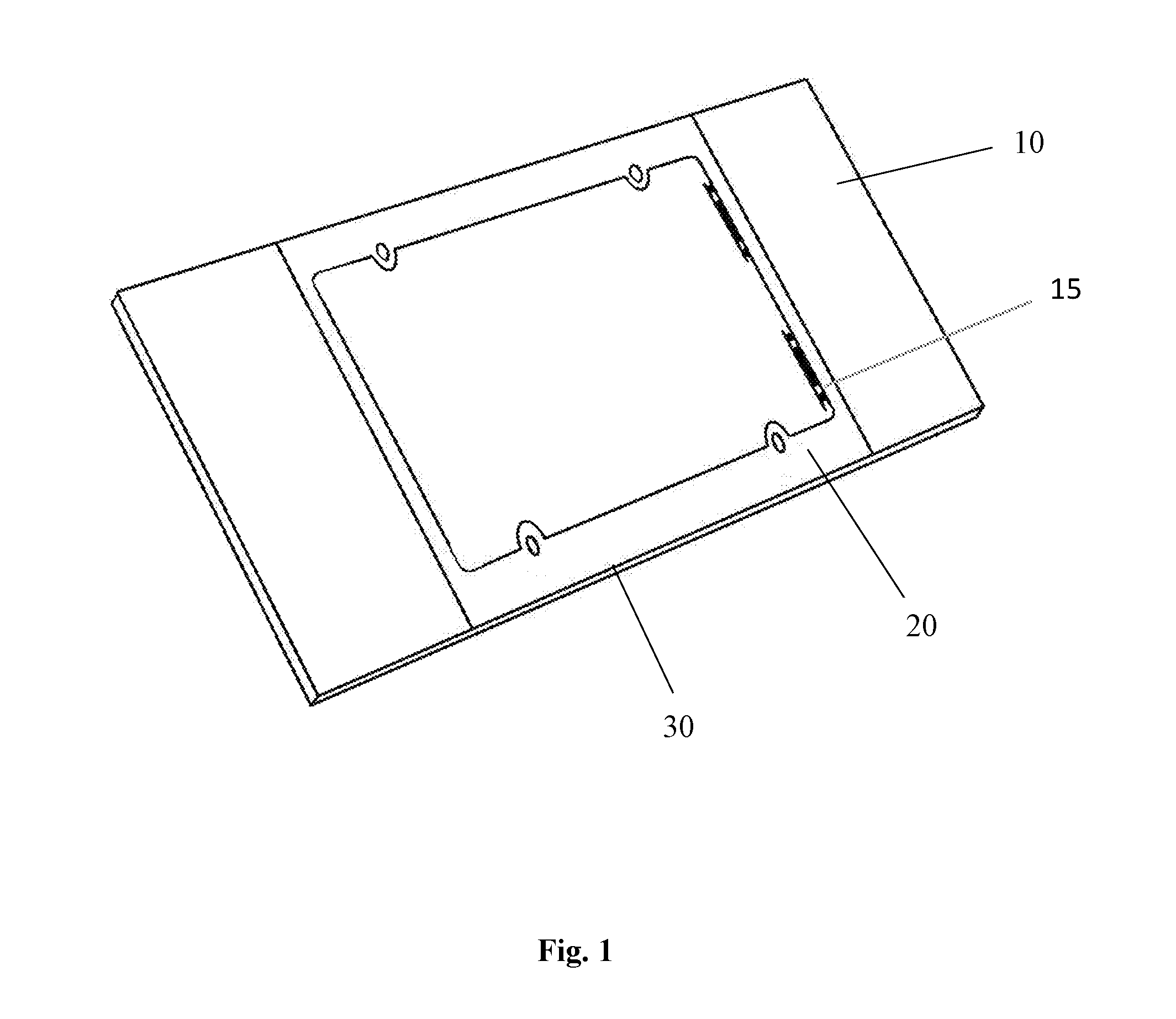
[0023]The invention disclosed comprises a central component 30 consisting of a frame fitted to surround a license plate. One or more panels incorporate one or more communication surfaces 10; the panels are either continuous with, or releaseably attached to one or more sides of the central component 30. The communication surface or surfaces 10 provide an area for removeable or changeable placement of messages, logos, advertisement, public service announcements or indicia. The central component's frame includes attachment apertures for mounting the device on a vehicle. Since vehicles often contain built in “hard points” for attachment of license plates, the frame can be attached utilizing the existing license plate attachment means at the vehicle and license plate interface as more fully described below.

[0024]A perspective view of a preferred embodiment of the device is shown in FIG. 1, illustrating several features, including a central component 30, which facilitates direct attachmen...


PUM


Abstract

This invention discloses a device and method for mounting and changeably displaying visual communications, including messages, logos, advertisement, public service announcements or indicia, on a vehicle. It incorporates a frame mounted on a license plate, optionally within the license plate recess at the front or rear of a vehicle, and utilizes panels that are continuous with or removeably attached to a central component framing the license plate in order to optimize visual appeal, minimize aerodynamic drag, and reduce or eliminate potential clearance issues. A removeably attachable panel configuration allows for panels to be mounted on one or both lateral sides, providing a means for customization based on a vehicle's exterior design or user preference.

Description

CROSS-REFERENCE TO RELATED APPLICATIONS[0001]This application claims priority to U.S. patent Application No. 62 / 105,014, filed Jan. 19, 2015.STATEMENT REGARDING FEDERALLY SPONSORED RESEARCH / DEVELOPMENT[0002]Not applicable.REFERENCE TO SEQUENCE LISTING, A TABLE, OR COMPUTER PROGRAM LISTING COMPACT DISC APPENDIX[0003]Not applicable.BACKGROUND OF THE INVENTION[0004]This invention relates to mounting solutions for visual communications. More specifically, it provides a platform that facilitates dissemination of readily observable information in a spatially efficient manner to surrounding observers. It involves a device and method for mounting visual communications, including text, pictures, logos, team insignia, advertisements or other indicia, to a vehicle.[0005]1. Brief Summary of the Invention[0006]The invention described herein comprises a mounting solution through which visual information can be placed for observers, including pedestrians, bystanders and occupants of other vehicles...

Claims


Application Information

Patent Timeline
Patent Type & Authority Applications(United States)
IPC IPC(8): B60R13/10B60R13/00
CPCB60R13/005B60R13/105G09F21/048G09F2007/1895
Inventor GEORGIADIS, FRANCOIS
Owner GEORGIADIS FRANCOIS
Why Eureka
Try Eureka