Method for Automatic Piloting of a Rotary Wing Aircraft Having at Least One Thruster Propeller, Associated Automatic Autopilot Device, and Aircraft

a technology of automatic piloting and rotary wing aircraft, which is applied in the direction of vehicle position/course/altitude control, process and machine control, instruments, etc., can solve the problems of generating penalizing aerodynamic drag, affecting the flight speed of the aircraft, and presenting a considerable pitching angle of the helicopter, so as to facilitate the workload and minimize the aerodynamic drag of the aircraft

Active Publication Date: 2018-03-15
EUROCOPTER
View PDF0 Cites 5 Cited by
  • Summary
  • Abstract
  • Description
  • Claims
  • Application Information

AI Technical Summary

Benefits of technology

[0016]The present invention thus seeks to propose a method of facilitating the workload on a pilot of a rotary wing aircraft having at least one propulsion propeller, the method possibly serving to minimize the aerodynamic drag of the aircraft.
[0019]The workload on the pilot is thus lightened, the pilot possibly concentrating solely on controlling two parameters, i.e. the longitudinal attitude and the longitudinal forward speed, for example, rather than controlling three parameters. In addition, the pilot can maneuver the aircraft by calling for an angle of attack that is optimized to minimize the aerodynamic drag of the aircraft.
[0032]This method is then simple, the pilot needing only to adjust a reference angle of attack prior to engaging the assisted mode of piloting for maintaining an angle of attack.
[0033]Furthermore, it is possible to modify the value of the reference angle of attack in flight.
[0039]It should be observed that in a first implementation, the pilot acts on the longitudinal attitude of the aircraft by controlling the cyclic pitch of the blades of the rotary wing. Since the aerodynamic angle of attack is maintained at a reference angle of attack, by controlling the longitudinal attitude using a cyclic flight control associated with at least one cyclic control system for controlling the cyclic pitch of the blades of the rotary wing, the pilot modifies the air-path slope of the aircraft. This provides advantageous piloting comfort.
[0064]For a rotary wing aircraft also having at least one fixed wing, it should be observed that the symbols displayed for illustrating the reference angle of attack or the current angle of attack enable the angle of attack of the fixed wing of the aircraft to be evaluated and thus make it possible to avoid the fixed wing stalling.

Problems solved by technology

At high speed, a helicopter thus presents a considerable pitching angle, and consequently a strongly nose-down longitudinal attitude.
It can be understood that at high speed, the helicopter presents a large nose-down aerodynamic angle of attack, which angle of attack generates penalizing aerodynamic drag.

Method used


Image

  • Method for Automatic Piloting of a Rotary Wing Aircraft Having at Least One Thruster Propeller, Associated Automatic Autopilot Device, and Aircraft
  • Method for Automatic Piloting of a Rotary Wing Aircraft Having at Least One Thruster Propeller, Associated Automatic Autopilot Device, and Aircraft
  • Method for Automatic Piloting of a Rotary Wing Aircraft Having at Least One Thruster Propeller, Associated Automatic Autopilot Device, and Aircraft

Examples


first embodiment

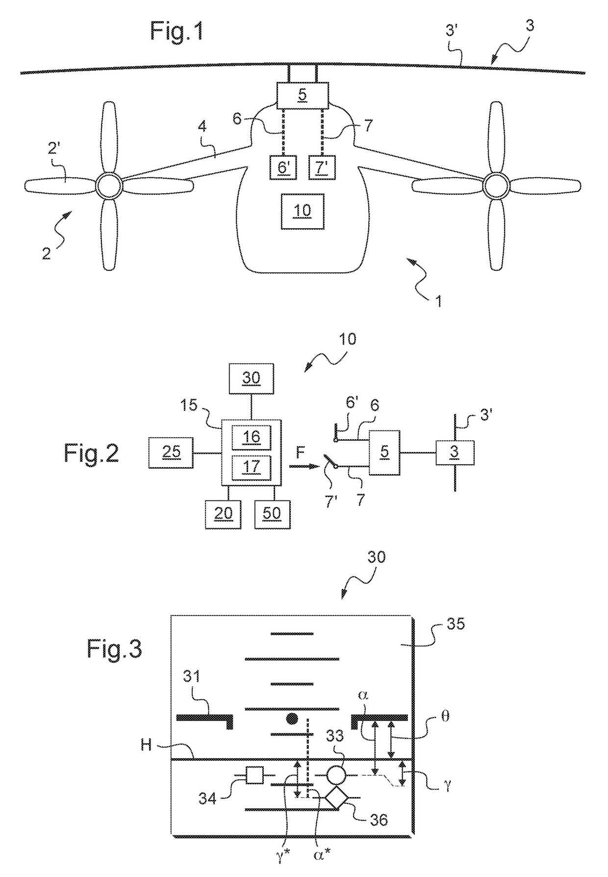
[0095]FIG. 2 shows a device 10 in a

[0096]Independently of the embodiment, the device 10 comprises a processor unit 15. The processor unit may comprise calculation means 16 that execute instructions stored in a memory 17.

[0097]As represented by arrow F, the processor unit 15 is then suitable in particular for controlling a collective control system 7 to modify the collective pitch of the second blade 3′, e.g. by controlling a parallel actuator and / or a series actuator of the collective control system 7.

[0098]To this end, the processor unit 15 may be connected to engagement means 20 for engaging an assisted mode of piloting for maintaining an angle of attack.

[0099]During this assisted mode of piloting for maintaining an angle of attack, the aerodynamic angle of attack a of the aircraft is automatically maintained equal to a reference angle of attack α* by automatically controlling the collective pitch of the second blades 3′. It can be understood that the term “the aerodynamic angle o...

second embodiment

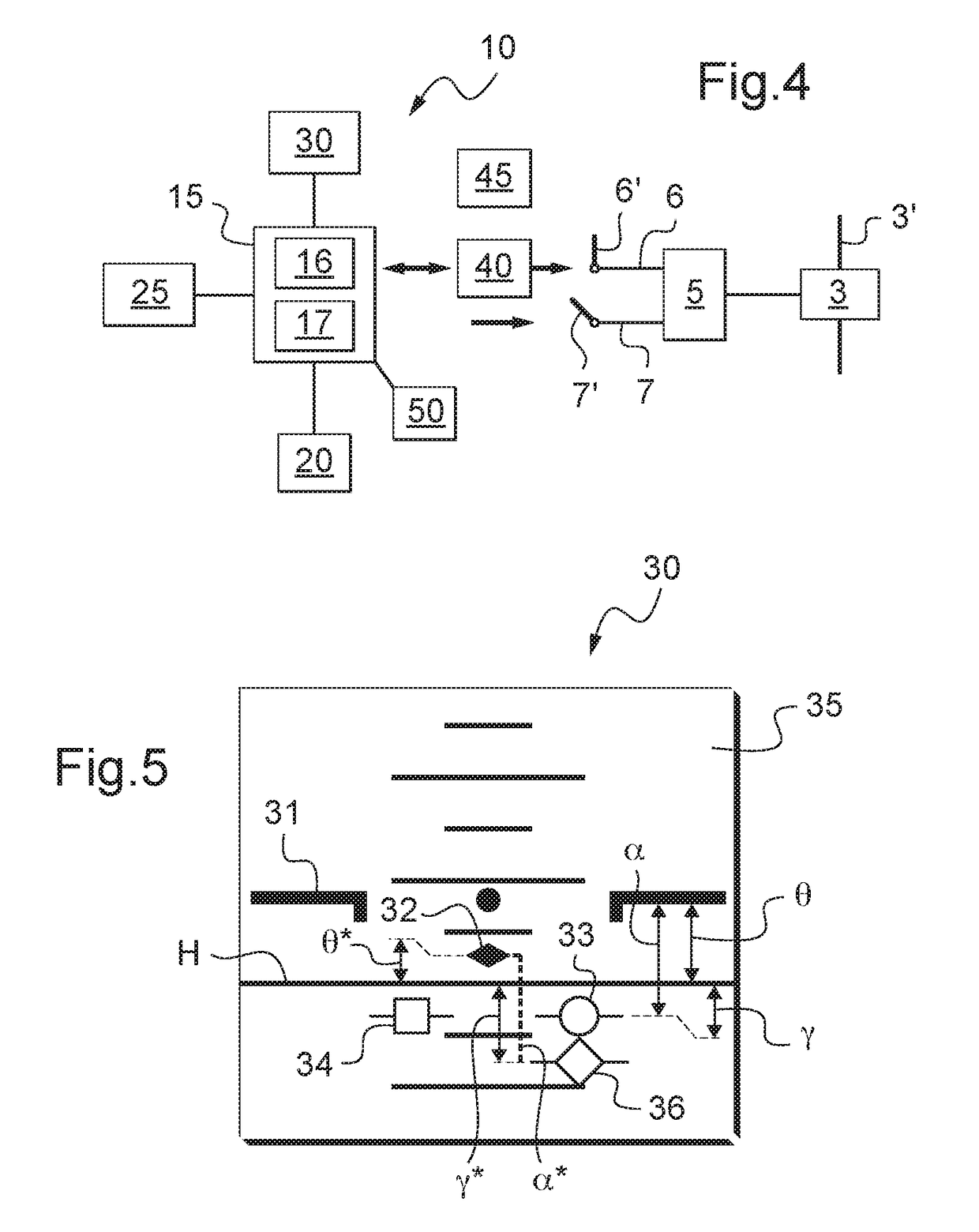
[0117]With reference to FIG. 4, in the second embodiment, the longitudinal attitude θ is automatically maintained equal to a reference longitudinal attitude θ*. The current longitudinal attitude is then equal to the reference attitude.

[0118]Consequently, the device 10 then controls an automatic system 40 to maintain a longitudinal attitude of the aircraft equal to a reference attitude. The device 10 may include an adjustment member 45 for adjusting the reference attitude, and indeed an engagement member for this embodiment.

[0119]It can be understood that the term “for maintaining a longitudinal attitude of the aircraft equal to a reference attitude” means that the longitudinal cyclic pitch of the blades 3′ is servo-controlled so that the current longitudinal attitude of the aircraft tends towards the reference attitude, or indeed is equal to the reference attitude.

[0120]The automatic system 40 co-operates with at least one longitudinal cyclic control system 6 for controlling the cyc...


PUM


Abstract

An autopilot device and method for automatically piloting a rotary wing aircraft, having at least one propulsion propeller, the rotary wing including at least one rotor with blades, the device including a processor co-operating with at least one collective control system for controlling the collective pitch of the blades. The device includes engagement means connected to the processor for engaging an assisted mode of piloting for maintaining an angle of attack, the processor automatically controlling the collective pitch of the blades when the assisted mode of piloting for maintaining an angle of attack is engaged by controlling the collective control system to maintain an aerodynamic angle of attack (α) of the aircraft at a reference angle of attack (α*).

Description

CROSS REFERENCE TO RELATED APPLICATIONS[0001]This application is a continuation of U.S. application Ser. No. 13 / 543,957, filed Jul. 9, 2012, which claims priority to FR 11 02191 filed on Jul. 12, 2011; the disclosures of which are incorporated in its entirety by reference herein.BACKGROUND OF THE INVENTION(1) Field of the Invention[0002]The present invention relates to a method of and device for automatically controlling a rotary wing aircraft having at least one propulsion propeller, to an autopilot device, and to an aircraft.(2) Description of Related Art[0003]The term “aircraft” includes in particular rotorcraft, i.e. aircraft provided with a rotary wing, and including helicopters.[0004]For example, a helicopter comprises a rotary wing that includes at least one main rotor for providing the helicopter with propulsion and lift.[0005]The longitudinal attitude and thus the pitching angle of the helicopter are then necessarily a function of the travel speed of the helicopter. At high...

Claims


Application Information

Patent Timeline
Patent Type & Authority Applications(United States)
IPC IPC(8): B64C27/57B64D45/00G05D1/08
CPCB64D45/00G05D1/0858B64C27/57B64C27/22
Inventor EGLIN, PAUL
Owner EUROCOPTER
Why Eureka
Try Eureka