X-ray fluorescence measuring system and methods for trace elements

a fluorescence measuring system and trace element technology, applied in the direction of material analysis using wave/particle radiation, x/gamma/cosmic radiation measurement, instruments, etc., can solve the problems of inability to measure trace elements, time-consuming wet chemistry methods dictated by standard laboratory methods, and inability to produce single analysis, etc., to achieve the effect of reducing interference, enhancing results, and maximizing emission efficiency

Inactive Publication Date: 2007-04-03
INDUTECH PROCESS CONTROL
View PDF39 Cites 34 Cited by
  • Summary
  • Abstract
  • Description
  • Claims
  • Application Information

AI Technical Summary

Benefits of technology

[0007]In one embodiment, an adjustable voltage X-ray tube is used as the source. This allows for the incident X-ray energies to be adjusted, preferably to within a range of 1.5–3.0 times the energy of the characteristic emission bands from the elements of interest to maximize the efficiency of emission. It is also possible to use filters to narrow the band of incident X-rays, which further reduces the amount of interference, as well as a slotted collimator for collimating the X-ray energy emitted from the source. Providing an optimal X-ray source:detector (sensor) geometry and positioning the sensor as close as possible to the surface of the material also enhances the results.

Problems solved by technology

While these XRF techniques work extraordinary well for measuring certain elements, such as sulfur, the ability to measure “trace elements” (e.g., vanadium, chromium, manganese, cobalt, nickel, copper, zinc, arsenic, selenium, and molybdenum) has previously been limited to laboratory techniques involving extensive preparation using pulverized samples.
The wet chemistry methods dictated by standard laboratory methods are time consuming and can only produce a single analysis in a matter of hours.
Turn around time in commercial laboratories is often days or weeks and the analysis is very expensive.
However, this patent does not mention the use of low energy XRF to measure trace elements, including gold.
Moreover, it dismisses L emission XRF techniques as inaccurate.
Furthermore, high energy XRF cannot be used to detect the K emission bands of the lighter trace elements with atomic numbers less than or equal to 48 (Cadmium).
Thus, the approach taught in the Robertson patent is not a solution to the problems identified in the foregoing paragraph.

Method used


Image

  • X-ray fluorescence measuring system and methods for trace elements
  • X-ray fluorescence measuring system and methods for trace elements
  • X-ray fluorescence measuring system and methods for trace elements

Examples


Embodiment Construction

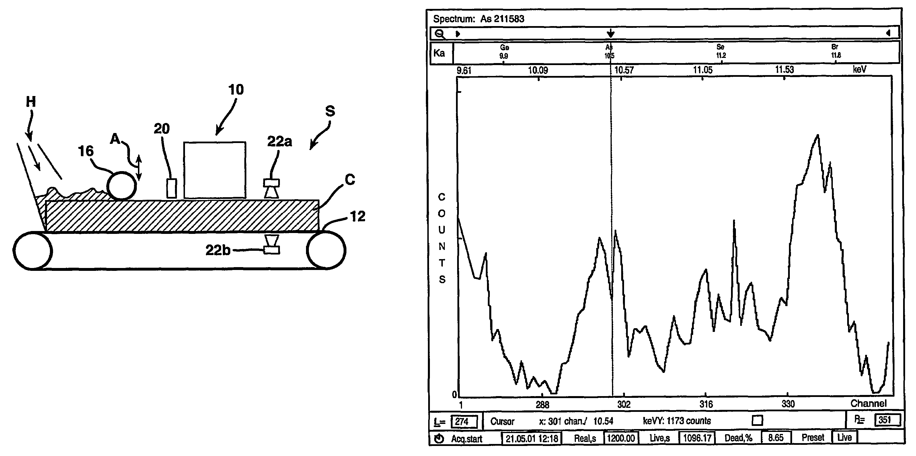
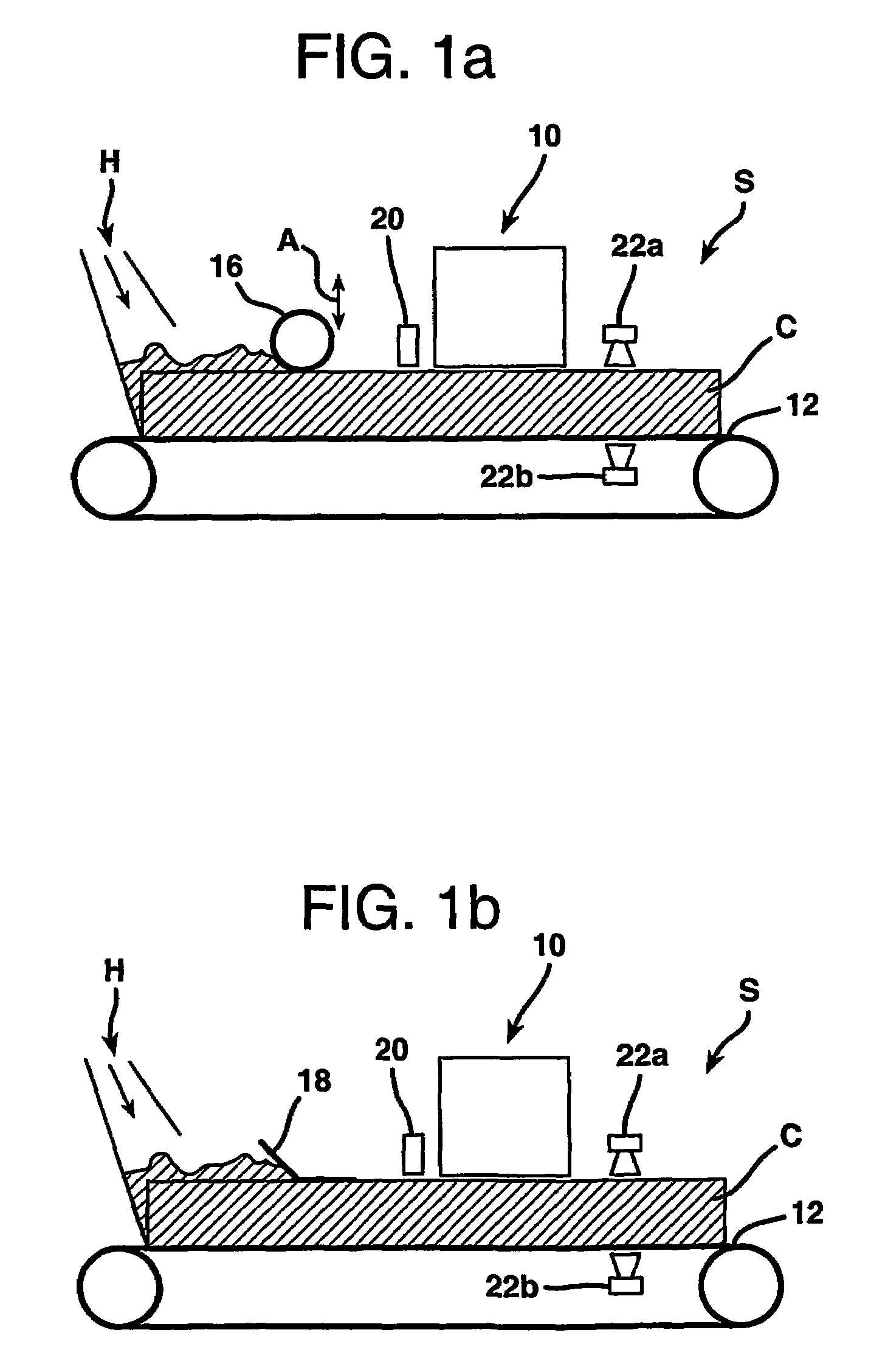
[0021]Reference is now made to FIGS. 1a and 1b, which show one embodiment of an XRF trace element sensor 10 mounted adjacent to an endless transfer conveyor belt 12 carrying a substance or material, such as coal C. The belt 12 and sensor 10 in combination may form part of a mechanical sampling system 14 for measuring the elemental composition of a sample of material, such as ore or coal C delivered from a chute H or the like. The sample may be supplied from a main conveyor line (not shown), and is preferably crushed or pulverized to have a particle size of approximately less than or equal to 10 millimeters (⅜ths of an inch) prior to being delivered to the sampling system 14.

[0022]In this system 14, a leveling structure and skirting (not shown) along the sides of the belt 10 together help to assure that a constant or substantially constant geometry of coal C or other substance is presented to the sensor 10 forming part of the system 14. In FIG. 1a, the leveling structure is shown as ...


PUM

PropertyMeasurementUnit
thicknessaaaaaaaaaa
angleaaaaaaaaaa
atomic numberaaaaaaaaaa

Abstract

An X-ray fluorescence measuring system and related measuring methods are disclosed, the system using X-ray energy at a level of less than 80 KeV may be directed toward a material, such as coal. The energy fluoresced may be detected (10) and used to measure the elemental composition of the material, including trace elements. The material may be moving or stationary.

Description

[0001]This application claims the benefit of U.S. Provisional Patent Application Ser. No. 60 / 317,257, filed Sep. 4, 2001, the disclosure of which is incorporated herein by reference.FIELD OF THE INVENTION[0002]In one aspect, this invention relates to measuring elements present in coal, ores, and other substances using energy dispersive X-ray fluorescence (XRF) spectroscopy. In another aspect, the invention relates to different apparatuses and methods for use in conjunction with elemental analyzers.BACKGROUND OF THE INVENTION[0003]Techniques for analyzing or measuring the elemental composition of a substance, such as coal, using X-ray fluorescence (XRF), are well-known in the art. An example of one technique is disclosed in U.S. Pat. No. 6,130,931, the disclosure of which is incorporated herein by reference. While these XRF techniques work extraordinary well for measuring certain elements, such as sulfur, the ability to measure “trace elements” (e.g., vanadium, chromium, manganese, c...

Claims


Application Information

Patent Timeline
Patent Type & Authority Patents(United States)
IPC IPC(8): G01N23/223
CPCG01N23/223G01N2223/076
Inventor LAURILA, MELVIN J.BACHMANN, CLAUS C.
Owner INDUTECH PROCESS CONTROL
Why Eureka
Try Eureka