Spinal implant assembly

Inactive Publication Date: 2006-03-16
STRYKER SPINE
View PDF38 Cites 127 Cited by
  • Summary
  • Abstract
  • Description
  • Claims
  • Application Information

AI Technical Summary

Benefits of technology

[0007] The present invention is directed towards a device for securing a spinal rod to a spine. The assembly may include an elongated spinal rod, a bone fixation element, a ball ring, a set screw and a rod connector. The elongated spinal rod is configured to be implanted adjacent to a spinal column of a patient and span across vertebral bodies. The bone fixation element of the assembly includes a bone engaging portion, as well as a stem portion. The ball ring of the present invention has an aperture that extends through the center of the ball ring and can slidably receive the spinal rod. Furthermore, t

Problems solved by technology

Each additional component or instrument required to assemble the fixation system adds to the complexity of the surgical technique.
Additionally, many of the known existi

Method used


Image

  • Spinal implant assembly
  • Spinal implant assembly
  • Spinal implant assembly

Examples


Embodiment Construction

[0029] Before describing several exemplary embodiments of the present invention, it is to be understood that the present invention is not limited to the details of construction or process steps set forth in the following description. The present invention is capable of other embodiments and of being practiced or carried out in various ways.

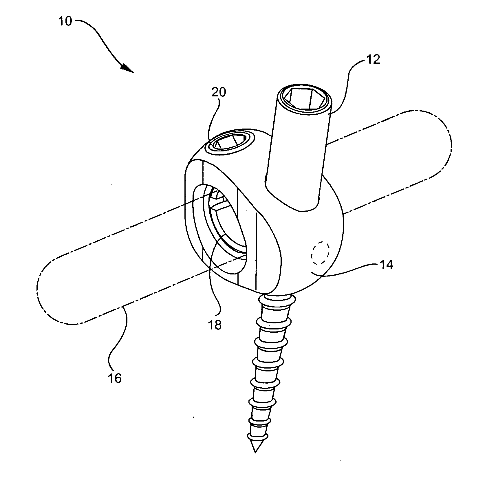
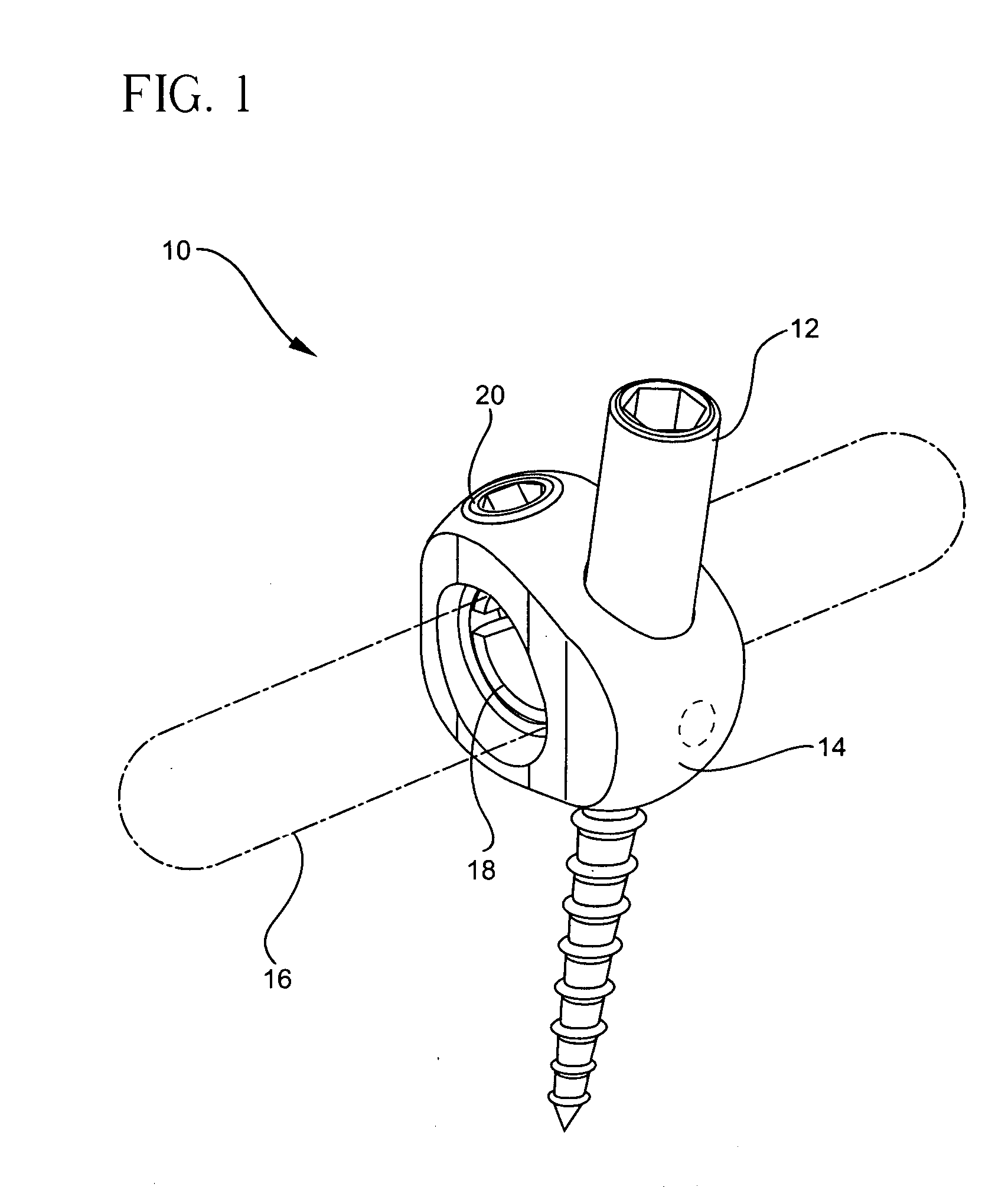
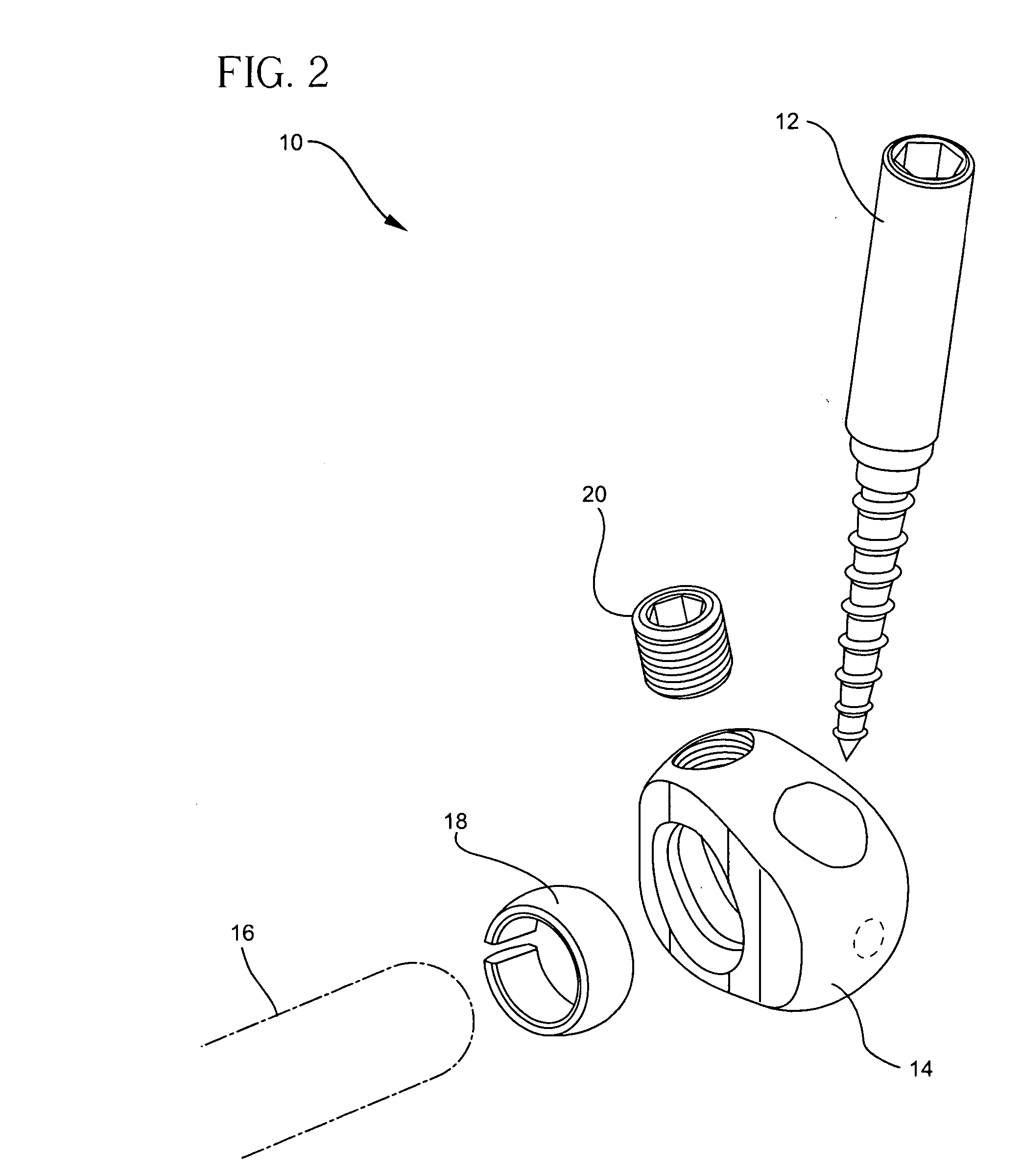
[0030] Referring now to the drawings and particularly to FIGS. 1-3, a bone fixation assembly 10, in accordance with certain preferred embodiments of the present invention is shown. The bone fixation assembly may include at least one fixation element 12 such as a bone screw, hook or anchor, a connector 14, an elongated spinal rod 16 which is preferably cylindrical, a ball ring 18, and a set screw 20. The bone fixation assembly 10 may be secured to the pedicles 11 of the vertebral bodies of a spinal column, as shown in FIG. 3.

[0031] Connector 14 of bone fixation assembly 10 is preferably made of a biological inert material, for example, any metal ...


PUM


Abstract

A device for securing a spinal rod to the spine. The device includes an elongated spinal rod configured to be implanted adjacent to the spinal column of a patient spanning across several vertebral bodies. The device also includes at least one fixation element for engaging vertebral bodies at a number of vertebral levels, each of the fixation elements having a vertebral engaging portion and a stem portion extending from the vertebral engaging portion. A ball ring having an aperture extending through the center of the ball ring. The ball ring further including a through slot so as to be compressible and expandable about a central axis extending through the center of the ball ring. The aperture is adapted to receive the spinal rod. The device further includes a set screw and a rod connector.

Description

BACKGROUND OF THE INVENTION [0001] The present invention relates to bone fixation devices and, in particular, to pedicle fixation assemblies and methods used in spinal fixation procedures. [0002] The spinal column is a highly complex system of bones and connective tissues that provide support for the body and protects the delicate spinal cord and nerves. The spinal column includes a series of stacked vertebral bodies, each vertebral body including an inner or central portion of relatively weak cancellous bone and an outer portion of relatively strong cortical bone. Situated between each vertebral body is an intervertebral disc that cushions and dampens compressive forces exerted upon the spinal column. A vertebral canal containing the spinal cord and nerves is located behind the vertebral bodies. [0003] A surgical technique commonly referred to as spinal fixation uses surgical implants for fusing together and / or mechanically immobilizing two or more vertebral bodies of the spinal co...

Claims


Application Information

Patent Timeline
IPC IPC(8): A61B17/70
CPCA61B17/7037A61B17/7041A61B17/704
Inventor DAVID, JEROME
Owner STRYKER SPINE
Why Eureka
Try Eureka