Printer apparatus
- Summary
- Abstract
- Description
- Claims
- Application Information
AI Technical Summary
Benefits of technology
Problems solved by technology
Method used
Image
Examples
first embodiment
[First Embodiment]
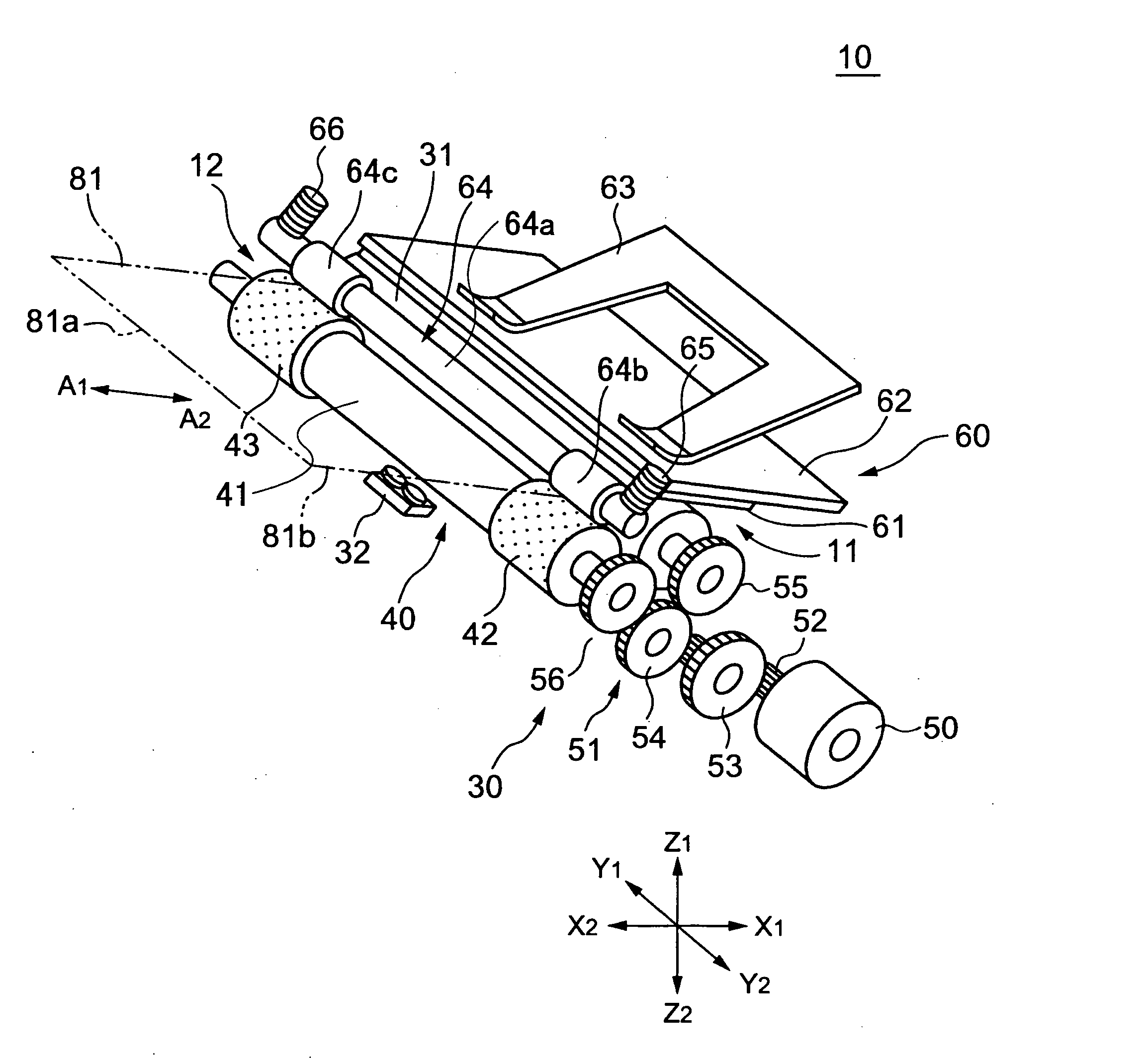
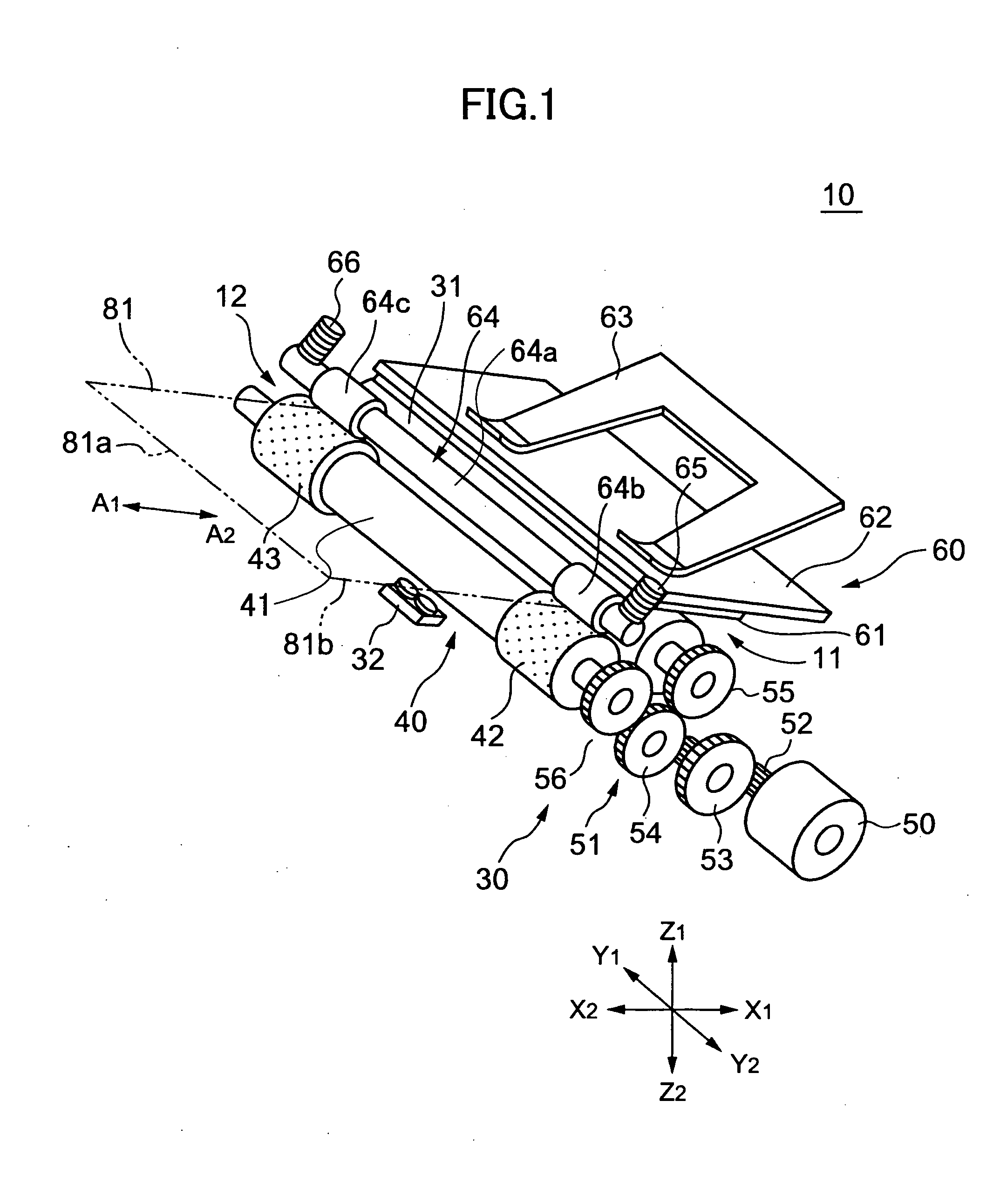
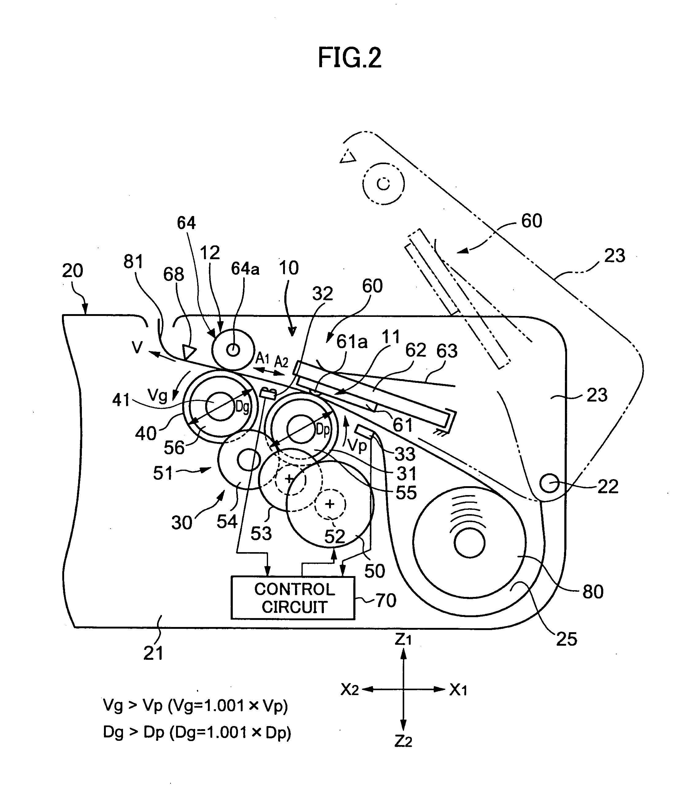
[0046]FIGS. 1 and 2 are drawings showing a thermal printer 10 according to a first embodiment of the present invention. The thermal printer 10 is a printer of a line printing type and is also of a clamshell type. X1-X2 indicates a longitudinal direction of the thermal printer 10, Y1-Y2 indicates a width direction of the thermal printer 10, and Z1-Z2 indicates a height direction of the thermal printer 10. A1 indicates a paper conveying direction, and A2 indicates a paper reversing direction.
[0047] The thermal printer 10 is assembled to a portable terminal apparatus 20. The portable terminal apparatus 20 includes a casing 21 and a cover 23 that is openably supported by an axial member 22 of the casing 21 at the X1 side. A paper roll installment portion 25 is disposed at the X1 side of the casing 21.
[0048] The thermal printer 10 has a main paper conveying portion 12 including a grip roller 40 serving as a driving roller and a pressing roller 64 serving as a driven r...
second embodiment
[Second Embodiment]
[0086]FIG. 11 is a schematic diagram showing a thermal printer 10A according to a second embodiment of the present invention. The thermal printer 10A has a structure where the sub-paper conveying portion 11 shown in FIG. 2 is separated into a sub-paper conveying part 11A-1 and a printing part 11A-2.
[0087] In an order of the sub-paper conveying part 11A-1, the printing part 11A-2, and the main paper conveying portion 12, said components are aligned in direction A1.
[0088] A first module 30A includes the platen roller 31, the grip roller 40, the pulse motor 50, and a speed deceleration gear alignment 51A, and the first and second paper (for example, reflection type) detecting sensors 32, 33, in which the components are supported by a frame (not shown). In an order of the second paper detecting sensor 33, the platen roller 31, a flat-shaped platen 90, the first paper detecting sensor 32, the grip roller 40, said components are aligned in direction A1. The speed dece...
third embodiment
[Third Embodiment]
[0093]FIG. 12 is a schematic diagram showing a thermal printer 10B according to a third embodiment of the present invention. The thermal printer 10B has a structure where the speed deceleration gear alignment 51 shown in FIG. 1 is replaced by an oscillating gear mechanism 100.
[0094] The oscillatory gear mechanism 100 includes a gear 101 fixed to a shaft of the grip roller 40, a V-shaped oscillatory arm member 102 (shaded gray) with the shaft of the grip roller 40 serving as its center for oscillation, and gears 103, 104 engaged with the gear 101, and supported by respective arm parts 102a, 102b of the oscillatory arm member 102. The arm member 102 and the grip roller 40 have a sliding clutch (not shown) disposed therebetween. By the rotation of the grip roller 40, the oscillatory arm member 102 is rotated via the frictional force of the sliding clutch until the gears are engaged in a direction same as the rotating direction of the grip roller 40.
[0095] The pulse ...
PUM
 Abstract
Description
Claims
Application Information
 - R&D
- Intellectual Property
- Life Sciences
- Materials
- Tech Scout
- Unparalleled Data Quality
- Higher Quality Content
- 60% Fewer Hallucinations
Browse by: Latest US Patents, China's latest patents, Technical Efficacy Thesaurus, Application Domain, Technology Topic, Popular Technical Reports.
© 2025 PatSnap. All rights reserved.Legal|Privacy policy|Modern Slavery Act Transparency Statement|Sitemap|About US| Contact US: help@patsnap.com


