Printer apparatus

a printing machine and printing technology, applied in the field of printing machines, can solve the problems of long period and difficulty in maintaining such performance, and achieve the effect of improving printing precision

Inactive Publication Date: 2007-05-08
FUJITSU COMPONENENT LTD
View PDF21 Cites 4 Cited by
  • Summary
  • Abstract
  • Description
  • Claims
  • Application Information

AI Technical Summary

Benefits of technology

[0018]According to an embodiment of the present invention, the peripheral velocity of the driving roller may be faster than the peripheral velocity of the platen roller.
[0024]It is another and more specific object of the present invention, for example, to provide a portable printer of a clamshell type that improves printing precision in a paper conveying direction without having to change the structure of a portion of a thermal head to which a rubber platen roller abuts.

Problems solved by technology

Although a satisfactory performance may be obtained in the early periods of using the rubber platen rollers, it is difficult to maintain such performance for a long period due to such factors as, for example, expansion / contraction caused from heat, deterioration with age, or wear.

Method used


Image

  • Printer apparatus
  • Printer apparatus
  • Printer apparatus

Examples


first embodiment

[First Embodiment]

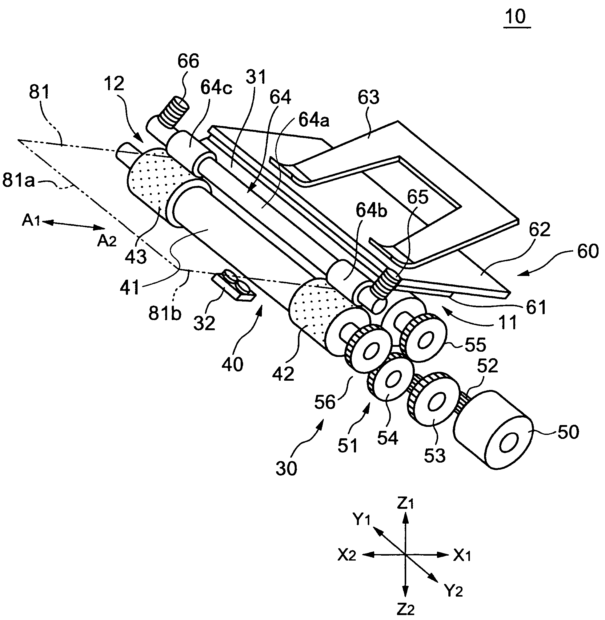
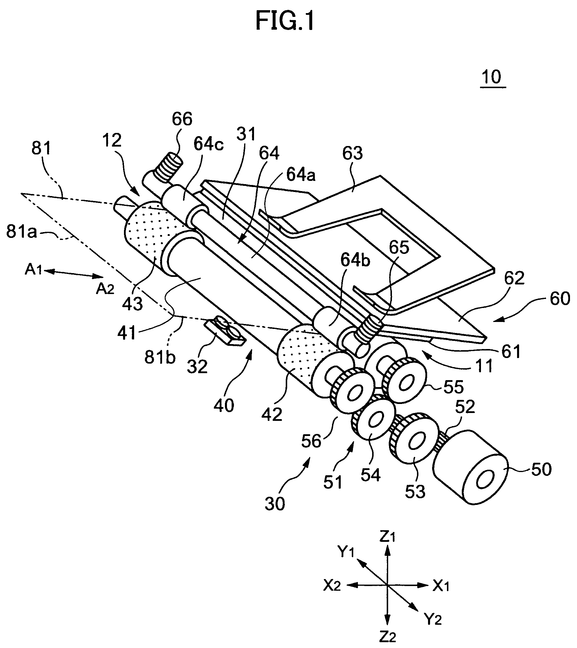
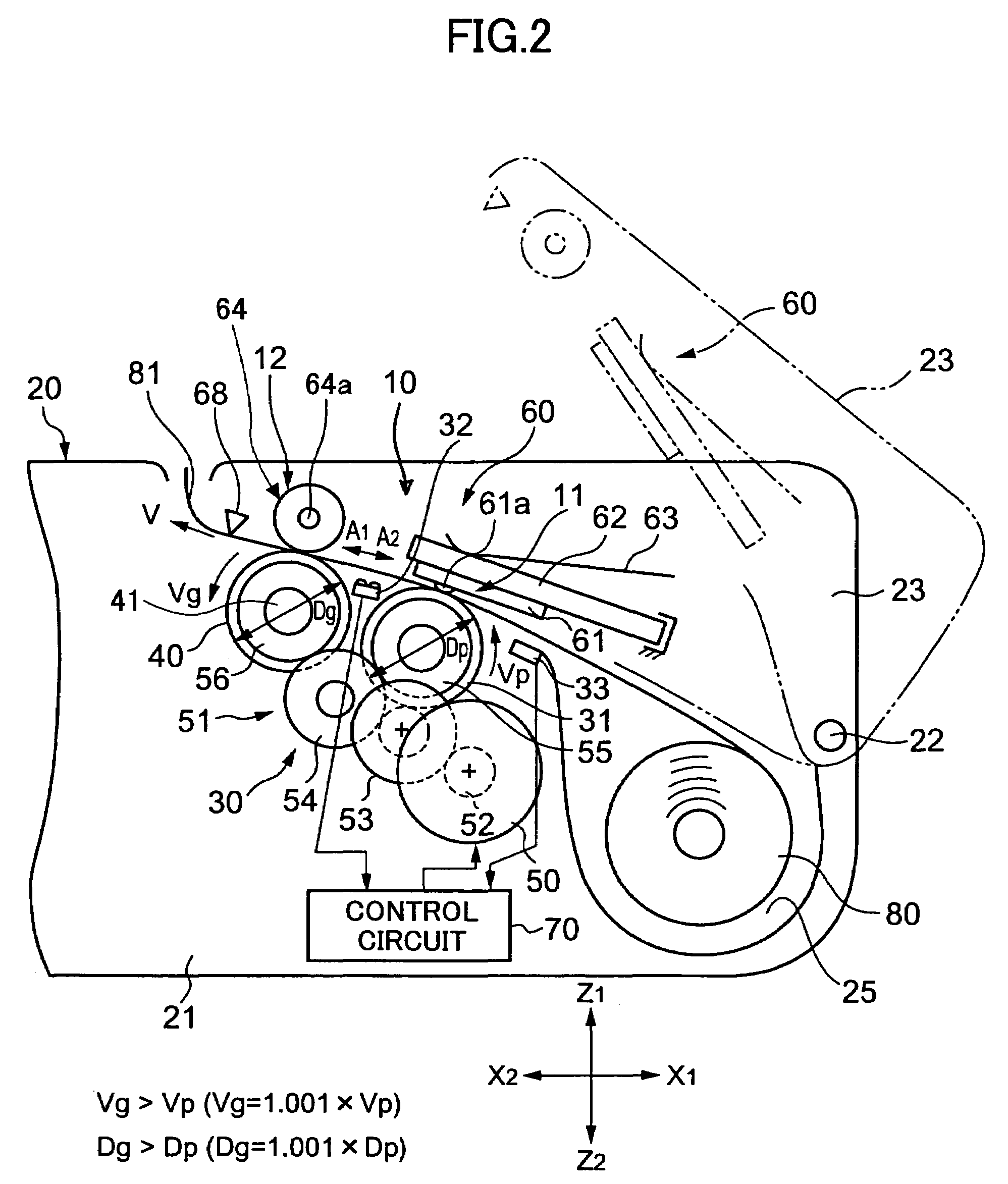
[0046]FIGS. 1 and 2 are drawings showing a thermal printer 10 according to a first embodiment of the present invention. The thermal printer 10 is a printer of a line printing type and is also of a clamshell type. X1-X2 indicates a longitudinal direction of the thermal printer 10, Y1-Y2 indicates a width direction of the thermal printer 10, and Z1-Z2 indicates a height direction of the thermal printer 10. A1 indicates a paper conveying direction, and A2 indicates a paper reversing direction.

[0047]The thermal printer 10 is assembled to a portable terminal apparatus 20. The portable terminal apparatus 20 includes a casing 21 and a cover 23 that is openably supported by an axial member 22 of the casing 21 at the X1 side. A paper roll installment portion 25 is disposed at the X1 side of the casing 21.

[0048]The thermal printer 10 has a main paper conveying portion 12 including a grip roller 40 serving as a driving roller and a pressing roller 64 serving as a driven rolle...

second embodiment

[Second Embodiment]

[0086]FIG. 11 is a schematic diagram showing a thermal printer 10A according to a second embodiment of the present invention. The thermal printer 10A has a structure where the sub-paper conveying portion 11 shown in FIG. 2 is separated into a sub-paper conveying part 11A-1 and a printing part 11A-2.

[0087]In an order of the sub-paper conveying part 11A-1, the printing part 11A-2, and the main paper conveying portion 12, said components are aligned in direction A1.

[0088]A first module 30A includes the platen roller 31, the grip roller 40, the pulse motor 50, and a speed deceleration gear alignment 51A, and the first and second paper (for example, reflection type) detecting sensors 32, 33, in which the components are supported by a frame (not shown). In an order of the second paper detecting sensor 33, the platen roller 31, a flat-shaped platen 90, the first paper detecting sensor 32, the grip roller 40, said components are aligned in direction A1. The speed decelera...

third embodiment

[Third Embodiment]

[0093]FIG. 12 is a schematic diagram showing a thermal printer 10B according to a third embodiment of the present invention. The thermal printer 10B has a structure where the speed deceleration gear alignment 51 shown in FIG. 1 is replaced by an oscillating gear mechanism 100.

[0094]The oscillatory gear mechanism 100 includes a gear 101 fixed to a shaft of the grip roller 40, a V-shaped oscillatory arm member 102 (shaded gray) with the shaft of the grip roller 40 serving as its center for oscillation, and gears 103, 104 engaged with the gear 101, and supported by respective arm parts 102a, 102b of the oscillatory arm member 102. The arm member 102 and the grip roller 40 have a sliding clutch (not shown) disposed therebetween. By the rotation of the grip roller 40, the oscillatory arm member 102 is rotated via the frictional force of the sliding clutch until the gears are engaged in a direction same as the rotating direction of the grip roller 40.

[0095]The pulse moto...


PUM


Abstract

A printer apparatus for printing data on paper traveling through the printer apparatus in a paper conveying direction. The printer apparatus includes a paper conveying portion including a driving roller and a driven roller, the driving roller and driven roller being moveable with respect to one another between an engaged position at which the driving roller and the driven roller are pressed together and a disengaged position at which the driving roller and the driven roller are separated; wherein the paper conveying portion is situated downstream, with respect to the paper conveying direction, from the location at which the data is printed on the paper; and wherein the driving roller and the driven roller are operative to pressingly sandwich the paper therebetween when the driving roller and the driven roller are in the engaged position.

Description

BACKGROUND OF THE INVENTION[0001]1. Field of the Invention[0002]The present invention generally relates to a printer apparatus, and more particularly to a portable thermal printer apparatus having a first module detachably attached to a second module.[0003]2. Description of the Related Art[0004]In recent years, there is a growing demand for portable thermal printers that can print, for example, barcodes and meter readouts. Compared to a general printer, a higher printing precision with respect to a paper conveying direction is required since barcodes and meter readouts are read by OCR (Optical Character Recognition).[0005]With a conventional portable thermal printer of a clamshell type, when a cover of the printer is closed, a platen roller formed of rubber, holding a sheet of paper, presses against a thermal head. The platen roller is rotated by a motor, and the paper is fed by the frictional force of the platen roller. A conventional example is shown in Japanese Laid-Open Patent A...

Claims


Application Information

Patent Timeline
Patent Type & Authority Patents(United States)
IPC IPC(8): B41J11/20B41J2/32B41J11/00B41J2/325B41J3/36B41J13/02B41J15/04B65H5/06
CPCB41J2/32B41J3/36B41J13/02B41J13/025B41J15/042B41J11/04
Inventor WATANABE, SUMIOSAKURAI, FUMIOMORI, YUKIHIROFUNADA, KUNIHIKO
Owner FUJITSU COMPONENENT LTD
Why Eureka
Try Eureka