Intrinsic Gauging For Tube Fittings

a technology of tube fittings and gauging, which is applied in the direction of hose connections, screws, instruments, etc., can solve the problems of inconvenient use of gauges, inability to verify additional axial displacement, and difficulty in keeping track of the number of rotations and fractions of pulling up the fittings

Inactive Publication Date: 2005-05-12
SWEGELOK CO +1
View PDF26 Cites 57 Cited by
  • Summary
  • Abstract
  • Description
  • Claims
  • Application Information

AI Technical Summary

Benefits of technology

[0012] To the accomplishment of the aforementioned and other objectives, and in accordance with one embodiment of the invention, an intrinsic gauging device includes a precisely formed and positioned marking on the coupling body that is visually perceptible when the coupling is in a finger tight position, and that is covered or visually imperceptible when the fitting has been properly pulled-up. In a preferred form, the marking is realized as a precision groove or recess machined

Problems solved by technology

Although the various parts of the fitting are machined with high precision and assembled to a finger tight position, it still can be difficult to keep track of the number of rotations and fractions thereof to pull-up the fitting.
Although the gauging tool described above continues

Method used


Image

  • Intrinsic Gauging For Tube Fittings
  • Intrinsic Gauging For Tube Fittings
  • Intrinsic Gauging For Tube Fittings

Examples


Embodiment Construction

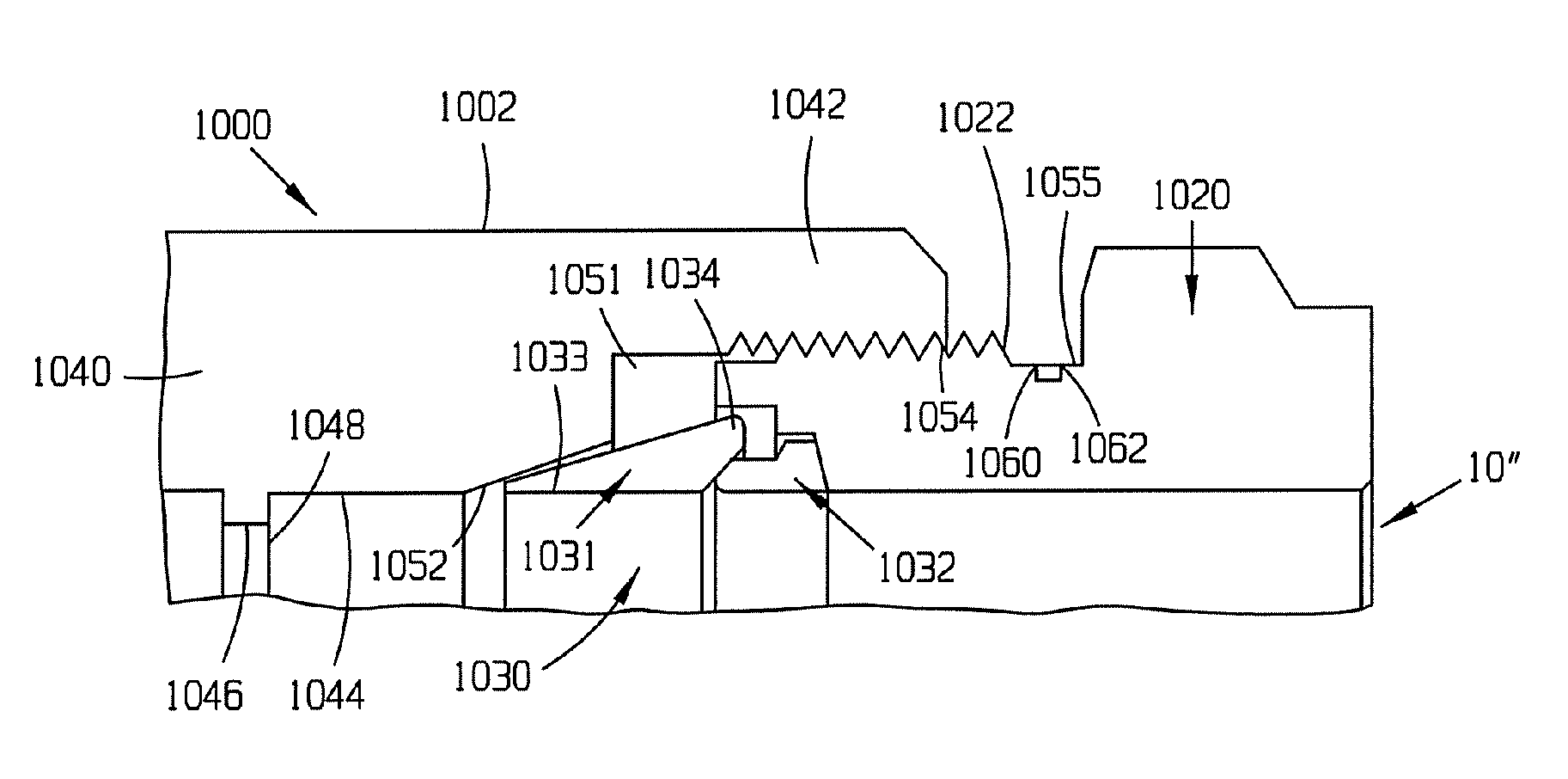
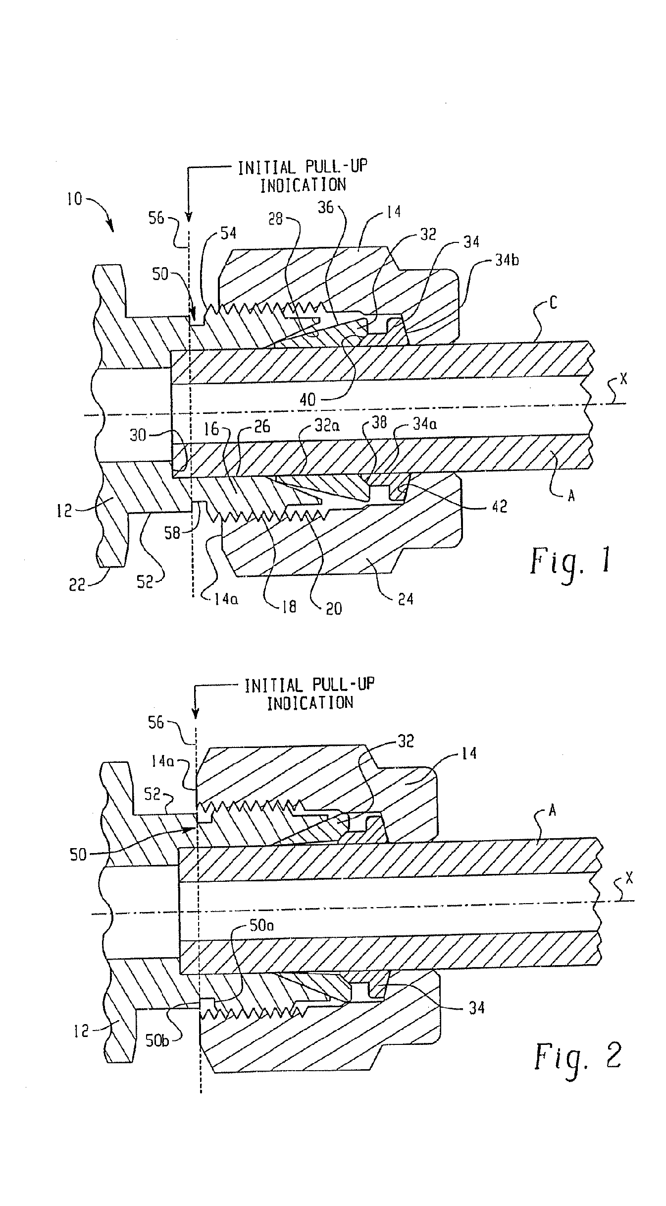
With reference to FIG. 1, the invention will be described herein in an exemplary manner as being incorporated into a standard two ferrule style tube fitting assembly. However, this description is intended to be exemplary in nature to explain and illustrate the concepts and advantages of the present invention, and therefore should not be construed in a limiting sense. Persons of mere ordinary skill in the art will readily understand and appreciate that the invention can be put to practice in a wide variety of tube fittings and couplings that are relatively rotated to make up the assembly. For example, and not for purposes of limitation, the present invention can conveniently be used in a single ferrule tube fitting or with any two part coupling in which proper assembly is determined in part by relative rotation between two threaded parts.

[0049] The standard fitting assembly 10 includes a coupling body 12 and a coupling nut 14. The coupling body 12 includes a first end 16 that is exte...


PUM


Abstract

An intrinsic gauging device for a ferrule type tube fitting of the type having a coupling nut, a coupling body and at least one ferrule, includes a precisely formed marking on the coupling nut that is visually perceptible that indicates the pull-up position of the tube fitting assembly.

Description

RELATED APPLICATIONS [0001] This application is a continuation in part of International Application No. 03 / 07739 filed Mar. 12, 2003, which claims priority to U.S. patent application Ser. No. 10 / 095,841 filed Mar. 12, 2002, now U.S. Pat. No. 6,640,457, which is a continuation in part of International Application No. 00 / 24900 filed Sep. 12, 2000, which claims the benefit of U.S. patent application Ser. No. 09 / 924,030 filed on Aug. 7, 2001 for INTRINSIC GAUGING FOR TUBE FITTINGS, now U.S. Pat. No. 6,502,323, which is a continuation of Ser. No. 09 / 395,386 filed on Sep. 13, 1999 for INTRINSIC GAUGING FOR TUBE FITTINGS, now U.S. Pat. No. 6,279,242, which also claims the benefit of U.S. Provisional Patent Application Ser. No. 60 / 159,965 filed on Oct. 18, 1999 for INTRINSIC GAUGING FOR TUBE FITTINGS, the entire disclosures of the aforementioned patent applications all of which are fully incorporated herein by reference.TECHNICAL FIELD OF THE INVENTION [0002] The present invention relates t...

Claims


Application Information

Patent Timeline
IPC IPC(8): F16L19/00F16L19/065F16L19/075
CPCF16L19/00F16L19/065F16L2201/60F16L2201/10F16L19/103
Inventor WILLIAMS, PETER C.JOHNSTON, LONNIE E.KARKOSIAK, JOHN D.BABUDER, GERALD A.MOGHE, SANJEEV S.
Owner SWEGELOK CO
Why Eureka
Try Eureka