Methods and structures for sealing air gaps in a building

a technology for sealing air gaps and building walls, applied in the direction of coatings, buildings, building components, etc., can solve the problems of gaps between the top plates of framed walls and drywall, significant air leakage, and few people even know that the gaps are presen

Inactive Publication Date: 2005-05-19
GRUNST KENNETH D
View PDF24 Cites 4 Cited by
  • Summary
  • Abstract
  • Description
  • Claims
  • Application Information

AI Technical Summary

Benefits of technology

[0014] allowing said elastomeric paint to dry and provide a seal in the air gap which maintains a seal during seasonal temperature changes.

Problems solved by technology

Some of that energy loss is due to wind, and some is due to the atmospheric pressure differences between the inside and the outside of the building.
A significant portion of the air leakage is due to the “chimney effect” or the escape of rising heated air from the house into the attic.
Air escapes through gaps that are virtually invisible, so few people even know that the gaps are present, let alone, how to seal the gaps.
Specifically, there are gaps between the top plates of framed walls and the drywall that is installed against them.
These gaps occur because of the imperfect fit and irregular size of the framing members.
The attic insulation above these gaps provides no defense.
Therefore, virtually every house in the U.S. was (and still is) built with pathways for continuous loss of air into the attic and covered with insulation that is ineffective in stopping the air movement.
This bead is highly ineffective since it becomes very rigid and creates wider voids than a wall without the bead.
The bead is also objectionable to builders and drywall installers since it may not enable the desirable close fit of wallboards.
However, this bead is often non-existent after the drywall is installed.
When the drywall is slid up the wall and into position during installation, the leading edge of the drywall wipes away most of the sealant bead and it remains on the edge of the drywall (in a totally ineffective location) rather than behind the drywall where it needs to be.
Attempts to change the installation habits of drywall hangers to preserve the bead have been unsuccessful.
The installers claim that the drywall sheets are too heavy and awkward to gently place them against the wall, and then hold them steady long enough to nail them into position without disrupting an uncured bead of caulk.
However, this method is ineffective since the drywall doesn't slide over the blunt edge of the weatherstrip tape.
It is unreasonable to expect that a drywall Installer, being paid on a piece-work basis, would reattach every piece of weather strip that tears loose.
In most cases, the tape simply “disappears” or remains on the leading edge of the drywall, and the homeowner is the loser, because the homeowner does not receive the energy saving device the owner thought he or she was buying.

Method used


Image

  • Methods and structures for sealing air gaps in a building
  • Methods and structures for sealing air gaps in a building
  • Methods and structures for sealing air gaps in a building

Examples


Embodiment Construction

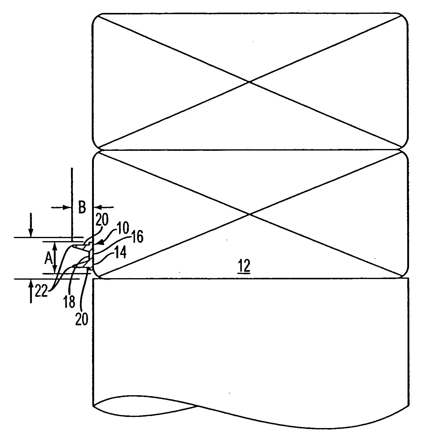
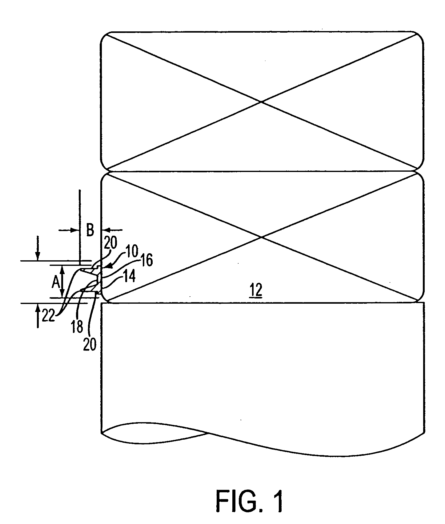
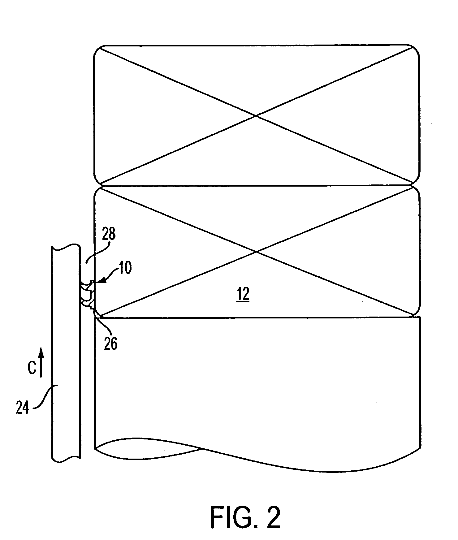
[0028] With reference to FIGS. 1 and 3, a seal structure, generally indicated at 10 and provided in accordance with the principles of the present invention, is shown coupled to a top plate or member 12 of a wall. The seal structure 10 is comprised of curable, flowable, non-sag material such as silicone caulk so as to be easily applied, for example, with conventional caulking equipment. The material of the seal structure 10 is preferably a silicone glazing adhesive / sealant which holds it shape without sagging when tooled. The material preferably has a neutral cure with no strong ammonia odor. Neutral cure silicones have an added advantage in that they cure due to atmospheric moisture, and therefore cure rapidly in virtually all temperature ranges experienced at a construction site. A preferred material has a medium modulus, which gives the material approximately 50% or more joint movement capability, exhibits a “skin” in about 5 to about 10 minutes after application, and achieves a f...


PUM


Abstract

Provided a method of sealing air gaps between floor joists and a band joist using an elastomeric paint sprayed under pressure to fill the air gaps.

Description

[0001] This application is a Continuation-in-Part of U.S. application Ser. No. 10 / 954,919, filed Oct. 1, 2004, which is a Divisional application of U.S. application Ser. No.10 / 654,004, filed Sep. 4, 2003, which is a Divisional application of Ser. No. 09 / 865,472, filed on May 29, 2001, now U.S. Pat. No. 6,651,402, which claims priority to U.S. Ser. No. 60 / 208,916, filed on Jun. 5, 2000, the complete disclosures of which are incorporated herein by reference.FIELD OF THE INVENTION [0002] This invention relates to sealing air gaps in the houses and commercial buildings to reduce energy loss due to air leakage through the gaps. BACKGROUND OF THE INVENTION [0003] Many experts believe that 40% or more of energy loss in a home is due to air leakage. Some of that energy loss is due to wind, and some is due to the atmospheric pressure differences between the inside and the outside of the building. A significant portion of the air leakage is due to the “chimney effect” or the escape of rising ...

Claims


Application Information

Patent Timeline
Patent Type & Authority Applications(United States)
IPC IPC(8): B05C17/005E04B1/68E04F21/165
CPCB05C17/00516E04F21/165E04B1/6801
Inventor GRUNST, KENNETH D.
Owner GRUNST KENNETH D
Why Eureka
Try Eureka