Safety/security alert system

a technology of safety and security, applied in the field of safety/security alert system, can solve the problems of ineffective emergency message delivery of ac powered televisions and radios to persons in the power outage area, inability to provide verification methods in notification systems, and a large number of missed messages

Inactive Publication Date: 2007-02-20
SPEED 3 ENDEAVORS
View PDF15 Cites 137 Cited by
  • Summary
  • Abstract
  • Description
  • Claims
  • Application Information

AI Technical Summary

Problems solved by technology

Although these methods may reach many of the intended recipients, they also miss a significant number.
Moreover, if the emergency has caused a power outage in an area, then AC powered televisions and radios are ineffective for delivering the emergency message to persons in the power outage area.
Moreover, such notification systems do not provide any method for verifying that an emergency message has been delivered to and received by the intended recipients.
However, not all communities have such sirens and / or loudspeakers.
Further, the use of sirens provides no information regarding the emergency and relies upon individual residents obtaining information from other sources.
However, if the area's phone system is down, residents may not be timely notified of the emergency.
Further, if a resident of a community does not have voice mail and is not in the house to pick up the phone, he or she will not receive the prerecorded notification.
Further, residents with cordless phones will not receive the notification if the electrical power is out.
If there is a need to contact a large number of residents in a wide-spread emergency, the ability to contact all residents in a sufficiently short period of time using phone banks may be problematic.
“Hunting” for the building where the request originated slows emergency service response time, which could have significant negative effect on the outcome of the emergency situation.
Another shortcoming of the '263 patent is that it does not provide for transmitting incoming emergency messages to a home or business from governmental agencies.

Method used


Image

  • Safety/security alert system
  • Safety/security alert system
  • Safety/security alert system

Examples


Embodiment Construction

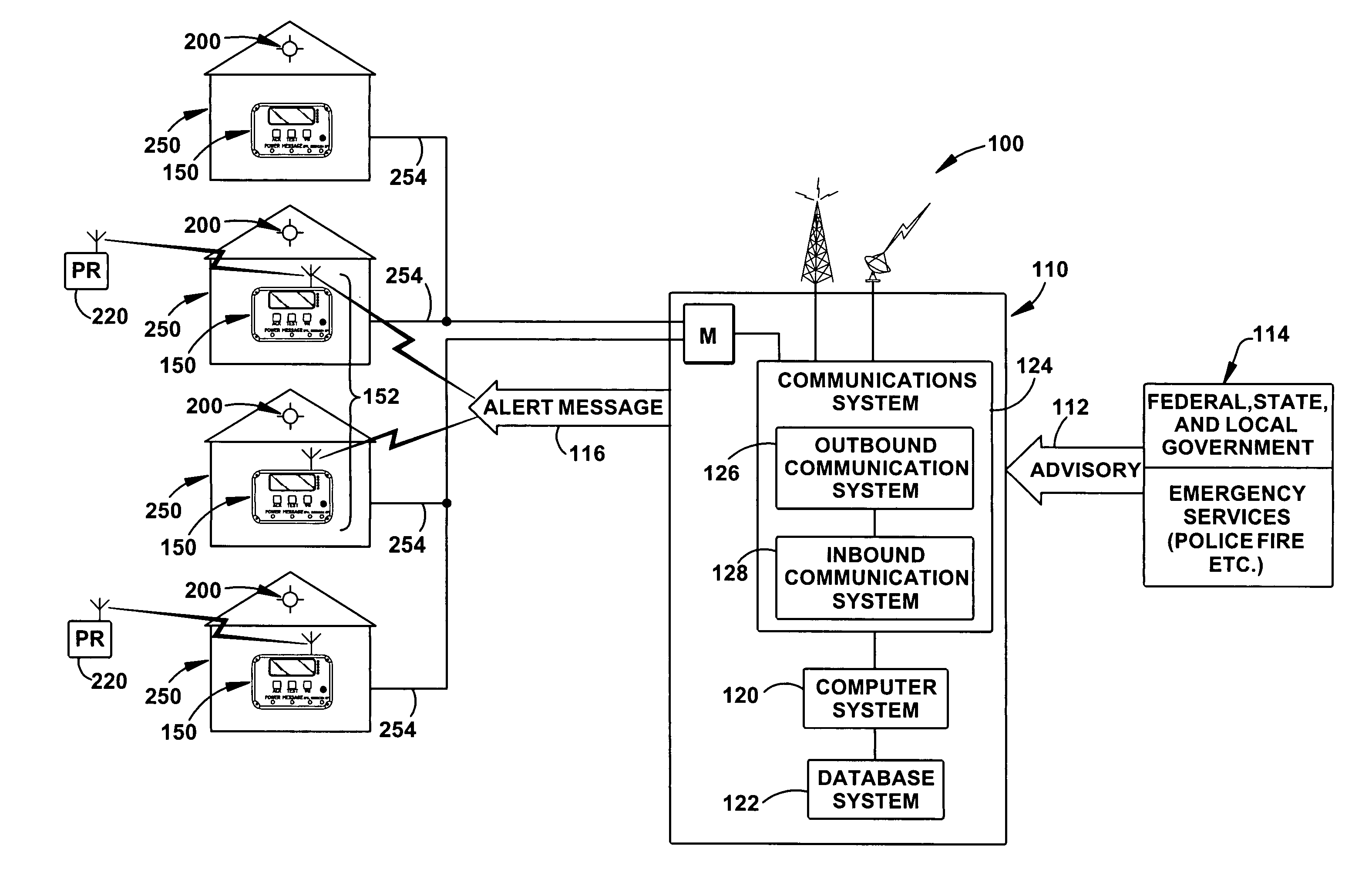
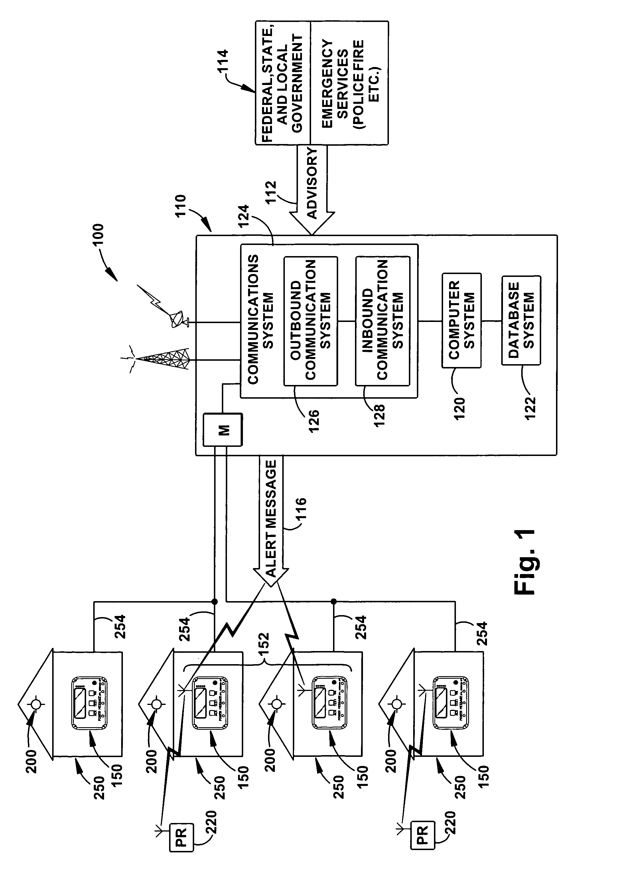
[0027]Turning to the drawings, a block diagram of a safety / security alert system of the present invention is shown generally at 100 in FIG. 1. The safety / security alert system 100 is comprised of two major subsystems, a central monitoring and control station or center 110 and a plurality of remote stations 150. Additionally, each of the plurality of remote stations 150 has associated with it at least one visible beacon 200 and may have one or more personal remotes 220 associated with it.

[0028]As will be discussed below, a beacon 200 includes an illumination source 202 that is actuated by its associated remote station 150. The remote stations 150 are disposed in or on buildings 250, e.g., residences (homes, apartments, condominiums), commercial buildings (businesses, schools, hospitals, etc.). The personal remote 220 is a small device designed to be carried by a user and can be used for requesting emergency services.

Central Monitor and Control Station 110

[0029]The central monitor and...


PUM


Abstract

A safety / security system that includes a central control station and a plurality of remote stations suitable for installation in residential and business buildings. The central control station receives public emergency warnings, notifications and advisories and transmits alert messages to select remote stations based on geographic or other criteria. Each remote station includes an identifier, a visual display, a user interface, and electronics for receiving the alert message from the central control center, processing the alert message to determine if the remote station is an intended recipient of the message by ascertaining if the alert message includes the remote station identifier and, if the remote station is an intended recipient of the alert message, utilizing the display to display information related to the alert message. The remote station also transmits an acknowledgement message to the central control station when a user of the remote station actuates the user interface to verify receipt of the information displayed on the display related to the alert message.

Description

CROSS-REFERENCE TO RELATED APPLICATION [0001]This application is a continuation-in-part of U.S. application Ser. No. 10 / 836,356, filed on Apr. 30, 2004, now abandoned.FIELD OF THE INVENTION [0002]The present invention relates to a safety / security alert system that includes a central monitor and control station and a plurality of remote stations suitable for installation in residences and businesses for providing safety and / or emergency alerts to users of the system and further providing a visible beacon to guide emergency personnel to a home or business location where emergency services have been requested.BACKGROUND ART [0003]Providing for public safety / security includes numerous functions such as notifying citizens of a community of health, safety and / or emergency situations, e.g., severe weather alerts, “Amber alerts” for missing children, areas to avoid because of accidents, fires, chemical spills, etc. Current methods used by federal, state and local governmental agencies and e...

Claims


Application Information

Patent Timeline
Patent Type & Authority Patents(United States)
IPC IPC(8): G08B1/08H04Q7/00G08B1/00G08B25/00G08B27/00
CPCG08B27/001G08B25/00
Inventor BANKERT, TROY WESLEYGAY, GREGORY ALANCLORE, CONNIE ANN
Owner SPEED 3 ENDEAVORS
Why Eureka
Try Eureka