LED lighting system

a technology of led lighting and led tubes, which is applied in the direction of vehicle components, signalling/lighting devices, aircraft crew accommodation, etc., can solve the problems of short life, disadvantages of fluorescent lamps for consumers, and limitations of the capabilities and usage of fluorescent lamps, so as to increase the reliability of led lighting tubes, the effect of high power leds and sufficient heat dissipation capability

Active Publication Date: 2007-08-09
LED SMART
View PDF22 Cites 140 Cited by
  • Summary
  • Abstract
  • Description
  • Claims
  • Application Information

AI Technical Summary

Benefits of technology

[0004] In accordance with an aspect of the invention, there is therefore provided a light emitting diode lighting device and system that can be used for illuminating the interior and / or exterior of vehicles, aircraft, watercraft, signage or buildings is provided. The system includes a voltage feedback constant current power supply circuitry and high power LEDs. The printed circuit assemblies are preferably firmly mounted onto a continuous or semi-continuous mounting channel case that also works as a heat sink. By this means, it not only increases the reliability of the LED lighting tube but also it provides sufficient heat dissipation capability for the heat generated by the LEDs. Since the operating temperature of the LEDs is controlled and stays in cool condition, it dramatically increases the LED's lifetime and efficiency. The end caps and pins of this LED lighting device are fully compatible with existing conventional fluorescent light fixtures and can directly replace those fluorescent lighting tubes in vehicles, mass-transit, watercrafts, aircrafts, signage or buildings with minimal modifications.
[0005] In further aspects of the invention, an LED lighting system has a housing forming a channel and being heat conductive and rigid, with one or both ends of the housing having electrical connectors for connection to a power source. An LED array extends along the housing within the channel, each LED in the LED array having a power rating of greater than 0.5 watt. Onboard current control circuitry for the LED array is carried by the housing, preferably within the channel, and may provide current control for individual sets of LEDs. The current control allows careful control of the forward current passing through the LED array so that it controls the brightness and heat production by the LEDs.

Problems solved by technology

The fluorescent lamp however has limitations on its capabilities and usages.
The fluorescent lamp has disadvantages to the consumer.
The disadvantages of the fluorescent lamp are the short life, easily broken, low durability, high costs of replacement, high costs of specialty lights, limited color selection, electromagnetic interference (EMI) which may be harmful to other electronic equipment.
The manufacturing of fluorescent lamps and debris from replaced lamps have a high environmental risks, as the chemicals inside of a fluorescent lamp are toxic.
Also the flicker effect of dying or improperly installed fluorescent lamps may be extremely harmful to individuals with certain medical conditions.
The constant inconsistency of fluorescent lighting colors is often a complaint of consumers who have to replace lamps on a regular basis.
A fluorescent system cannot be used effectively in extreme low or high ambient temperatures.

Method used


Image

  • LED lighting system
  • LED lighting system
  • LED lighting system

Examples


Embodiment Construction

[0045] In this patent document, “comprising” means “including”. In addition, a reference to an element by the indefinite article “a” does not exclude the possibility that more than one of the element is present.

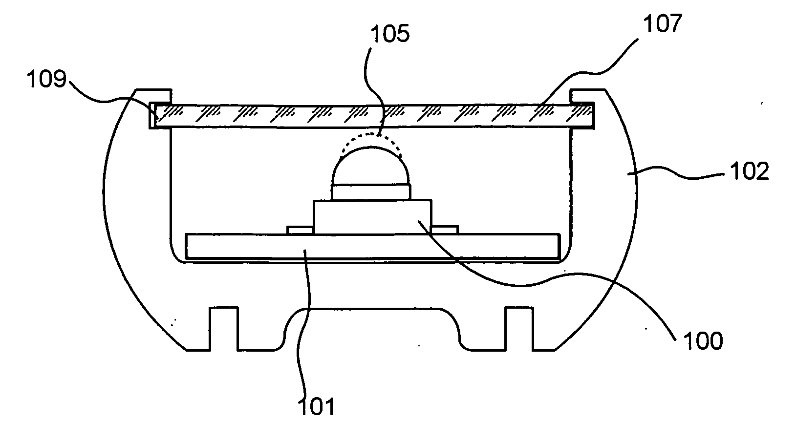
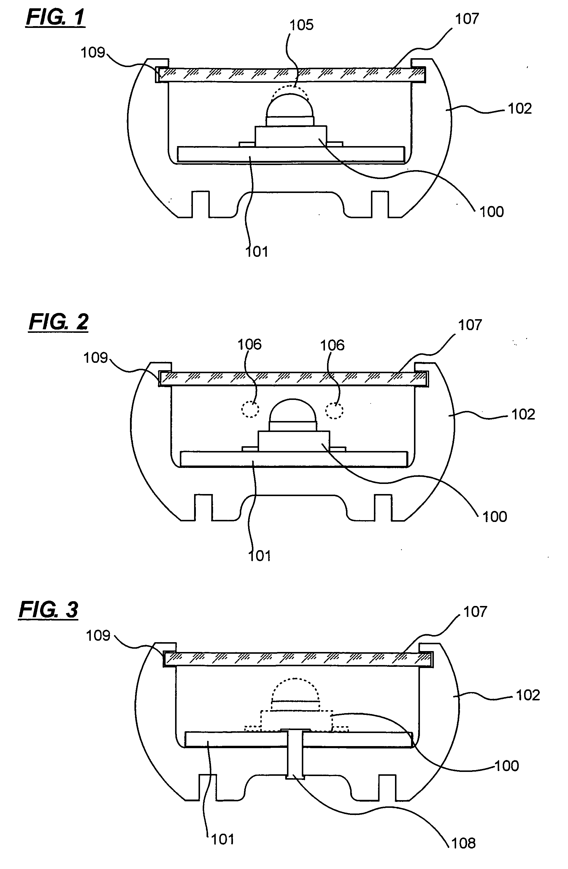
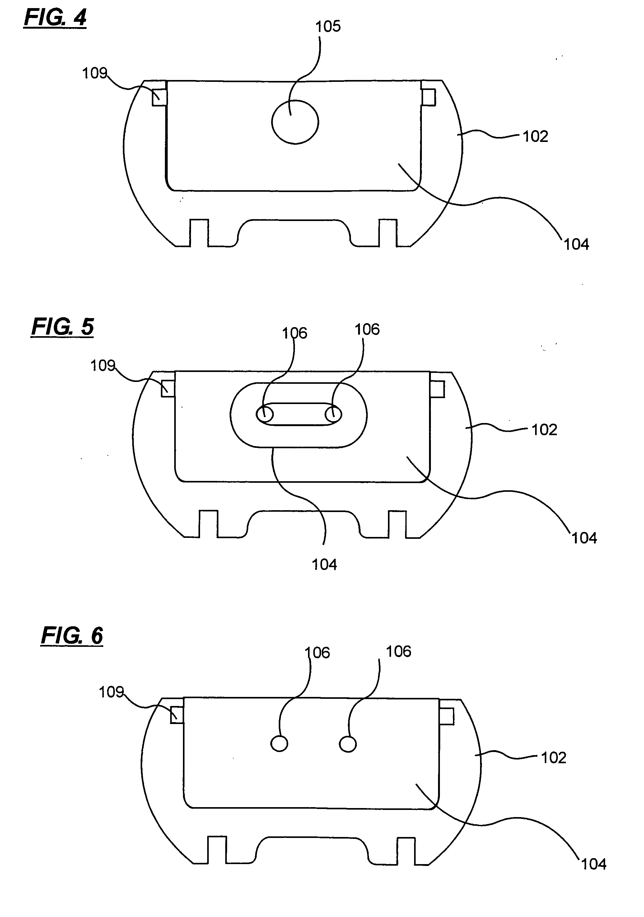
[0046] In FIGS. 1-3, 7-12, there is shown an exemplary LED lighting system 10 that includes a plurality of LEDs 100, each LED 100 being supplied power from a circuit board 101 supported by housing 102. Housing 102 forms a channel and is made of a heat conductive and rigid material, such as aluminum or any thermally conductive formable material. In one embodiment, the housing 102 is both heat conductive and rigid and is made of a unitary piece of material. The housing 102 is rigid and extends from end to end of the LED lighting system 10. The heat sink capability may be continuous from end to end or may be semi-continuous. In the case of being semi-continuous, the material providing the heat sink function may have breaks, in which case additional connector material is require...


PUM


Abstract

A light emitting diode lighting device and system that can be used for illuminating the interior and/or exterior of vehicles, aircraft, watercraft, signage or buildings is provided. It includes a voltage feedback constant current power supply circuitry and high power LEDs. The printed circuit assemblies are firmly mounted onto a continuous or semi-continuous mounting channel case that also works as a heat sink. By this means, it not only increases the reliability of the LED lighting tube but also it provides sufficient heat dissipation capability for the heat generated by the LEDs. Since the operating temperature of the LEDs is controlled and stays in cool condition, it dramatically increases the LED's lifetime and efficiency. The end caps of this LED lighting device are fully compatible with existing conventional fluorescent light fixtures and can directly replace those fluorescent lighting tubes in vehicles, mass-transit, watercrafts, aircrafts, signage or buildings with minimal modifications.

Description

BACKGROUND OF THE INVENTION [0001] The presented invention relates to a retrofit and direct replacement of conventional fluorescent lighting tubes with light emitting diode (LED) lighting devices for usage in vehicles, including mass-transit vehicles such as buses, trains, subway trains, also for lighting watercrafts, aircrafts, signage, or buildings using LEDs. [0002] For many years the lighting of interiors of vehicles, aircraft, buildings, signage, and watercraft, and more recently the lighting of exteriors of vehicles, and signage have use the cold cathode lamp; more commonly known as the fluorescent lamp or a fluorescent system. The fluorescent lamp however has limitations on its capabilities and usages. The fluorescent lamp has disadvantages to the consumer. The disadvantages of the fluorescent lamp are the short life, easily broken, low durability, high costs of replacement, high costs of specialty lights, limited color selection, electromagnetic interference (EMI) which may ...

Claims


Application Information

Patent Timeline
Patent Type & Authority Applications(United States)
IPC IPC(8): F21S8/00H05B44/00
CPCB60Q1/2611F21K9/17F21V27/02F21W2101/02F21W2101/06F21Y2101/02F21Y2103/003H05B33/0803H05B33/0815Y02B20/383Y02B20/386Y10S362/80F21V17/104F21V3/02F21V17/002B60Q3/025F21S4/20B64D2011/0038F21K9/00G09F13/04F21Y2103/10F21Y2115/10F21V23/005B60Q3/43B60Q3/78F21K9/278F21K9/66B64D2203/00F21S43/19F21S43/195F21S43/14F21S43/15F21S43/50F21S45/47F21W2107/10F21W2107/30H05B45/345H05B45/3725H05B45/3578H05B45/56Y02B20/30F21V29/70
Inventor SHAN, XINXIN
Owner LED SMART
Why Eureka
Try Eureka