Dynamic route discovery for optical switched networks using peer routing

a dynamic routing and optical switch technology, applied in the field of optical switches, can solve the problems of slow operation, traffic bottleneck in optical switch networks, and current optical switch technologies cannot efficiently support “bursty” traffi

Active Publication Date: 2005-05-19
INTEL CORP
View PDF77 Cites 149 Cited by
  • Summary
  • Abstract
  • Description
  • Claims
  • Application Information

AI Technical Summary

Problems solved by technology

O-E-O conversion at each switching node in the optical network is not only a very slow operation (typically about ten milliseconds), but it is very costly, and potentially creates a traffic bottleneck for the optical switched network.
In addition, the current optical switch technologies cannot efficiently support “bursty” traffic that is often experienced in packet communication applications (e.g., the Internet).
Thus, these WDM switches tend to be complex and very expensive to manufacture.

Method used


Image

  • Dynamic route discovery for optical switched networks using peer routing
  • Dynamic route discovery for optical switched networks using peer routing
  • Dynamic route discovery for optical switched networks using peer routing

Examples


Embodiment Construction

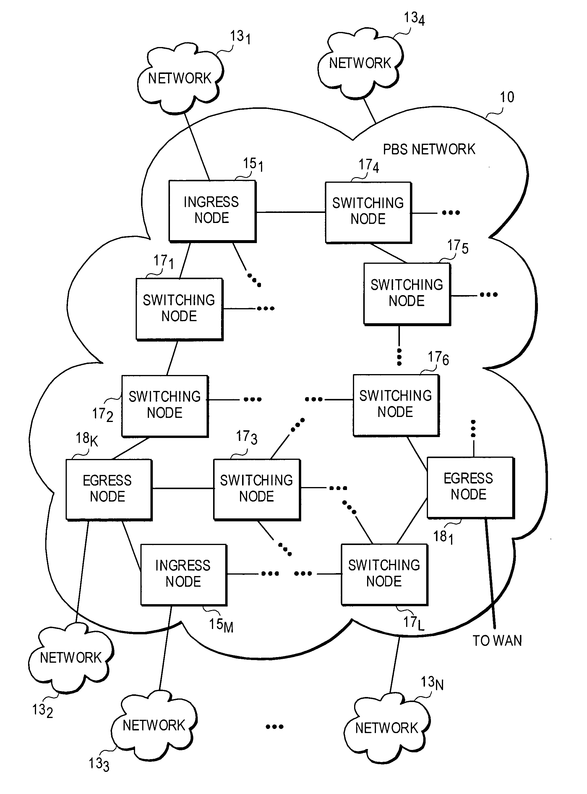
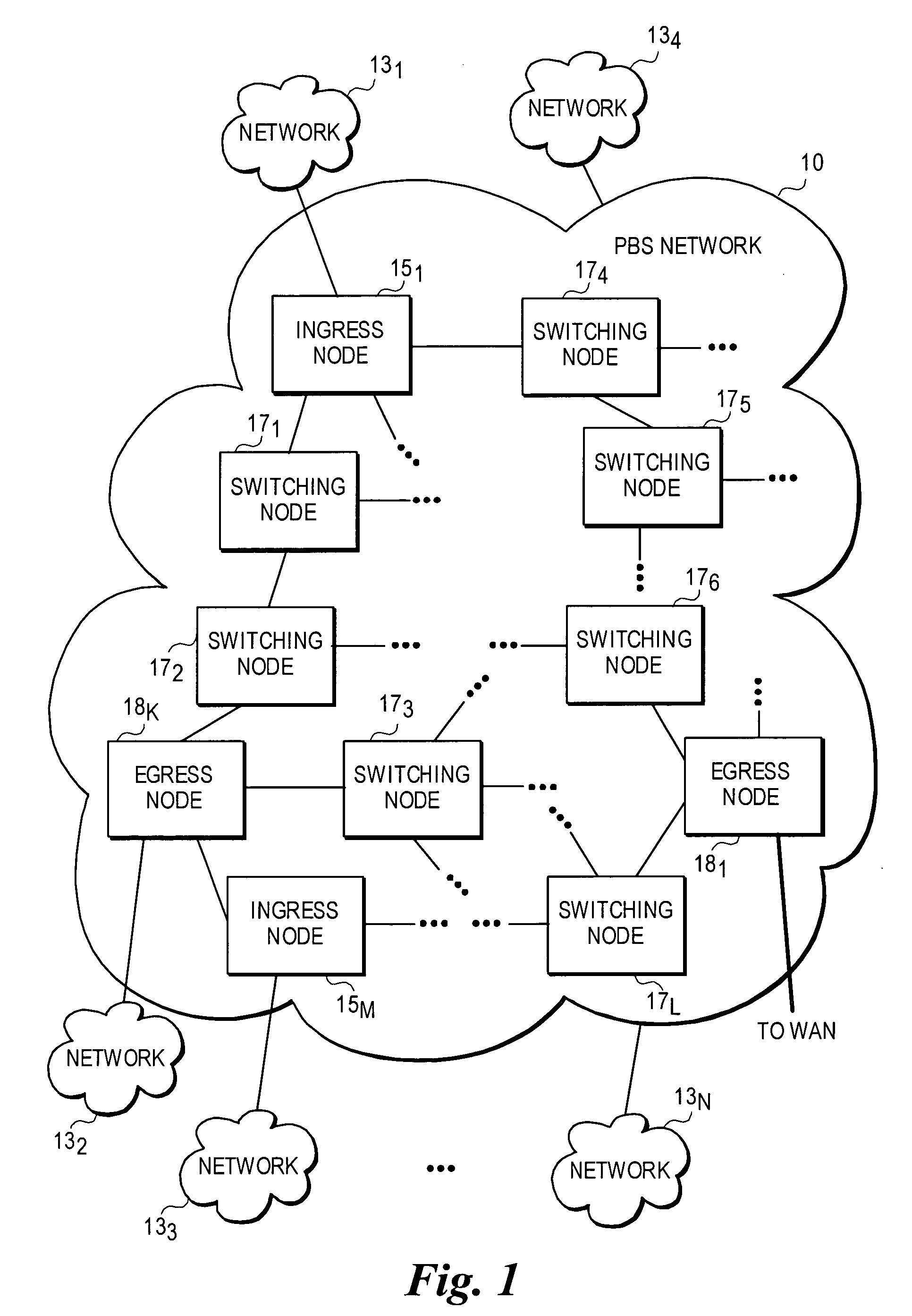
[0030] In the following detailed descriptions, embodiments of the invention are disclosed with reference to their use in a photonic burst-switched (PBS) network. A PBS network is a type of optical switched network, typically comprising a high-speed hop and span-constrained network, such as an enterprise network. The term “photonic burst” is used herein to refer to statistically-multiplexed packets (e.g., Internet protocol (IP) packets or Ethernet frames) having similar routing requirements. Although conceptually similar to backbone-based OBS networks, the design, operation, and performance requirements of these high-speed hop and span-constrained networks may be different. However, it will be understood that the teaching and principles disclosed herein may be applicable to other types of optical switched networks as well.

[0031]FIG. 1 illustrates an exemplary photonic burst-switched (PBS) network 10 in which embodiments of the invention described herein may be implemented. This embo...


PUM


Abstract

An architecture and method for performing dynamic route discovery and time slot reservation provisioning within optical-switched networks. The method employs extensions to the RSVP-TE signaling protocol, which uses various messages to reserve resources. Under a peer routing embodiment, routing trees and resource availability data are maintained by the edge nodes. A lightpath route is dynamically selected based on selection criteria applied to the routing tree data and the availability of resources along the lightpath. Link state information, including resource reservation data, is broadcast by the switching nodes to update the edge nodes of their resource availability. A resource reservation message is passed between nodes defined by an explicit route contained in the message, and resource availability is confirmed for the entire lightpath prior to confirming the resource reservations.

Description

CROSS REFERENCE TO RELATED APPLICATIONS [0001] The present application is related to U.S. patent application Ser. No. 10 / 126,091, filed Apr. 17, 2002; U.S. patent application Ser. No. 10 / 183,111, filed Jun. 25, 2002; U.S. patent application Ser. No. 10 / 328,571, filed Dec. 24, 2002; U.S. patent application Ser. No. 10 / 377,312 filed Feb. 28, 2003; U.S. patent application Ser. No. 10 / 377,580 filed Feb. 28, 2003; U.S. patent application Ser. No. 10 / 417,823 filed Apr. 16, 2003; U.S. patent application Ser. No. 10 / 417,487 filed Apr. 17, 2003; U.S. patent application Ser. No. ______ (Attorney Docket No. 42P16183) filed May 19, 2003, U.S. patent application Ser. No. ______ (Attorney Docket No. 42P16552) filed Jun. 18, 2003, U.S. patent application Ser. No. ______ (Attorney Docket No. 42P16847) filed Jun. 24, 2003, U.S. patent application Ser. No. ______ (Attorney Docket No. 42P17373) filed Aug. 6, 2003, and U.S. patent application Ser. No. ______ (Attorney Docket No. 42P17541) filed Oct. 22...

Claims


Application Information

Patent Timeline
Patent Type & Authority Applications(United States)
IPC IPC(8): H04L12/56H04Q11/00
CPCH04L12/5695H04L45/62H04L47/724H04L47/762H04L47/805H04Q2011/0088H04L47/825H04L47/829H04Q11/0062H04Q2011/0073H04L47/822H04L47/70
Inventor OVADIA, SHLOMOMACIOCCO, CHRISTIAN
Owner INTEL CORP
Why Eureka
Try Eureka