
Gasket, a bipolar battery and a method for manufacturing a bipolar battery with such a gasket

Active Publication Date: 2005-05-19
NILAR INT AB
View PDF12 Cites 36 Cited by
  • Summary
  • Abstract
  • Description
  • Claims
  • Application Information

AI Technical Summary

Benefits of technology

[0010] One possible object of an embodiment of the present application may be to provide a gasket that will simplify the manufacturing process of a bipolar battery.
[0011] A further possible object of an embodiment may be to provide a bipolar battery that is easy to manufacture.
[0012] Still a further possible object of an embodiment of the invention may be to provide a method for manufacturing a bipolar battery, using the gasket, that is simplified compared to prior art methods.
[0013] One possible advantage of an embodiment of the present invention is that more energy may be stored in the battery compared to prior art batteries. This is because the gasket can act as a hydrophobic barrier, a pressure tight sealing and provides means to create a common gas space within the battery. This in turn may make it possible to more efficiently use the available space and larger electrodes may be used compared to prior art batteries.
[0014] Another advantage is that the present invention provides additional cost and assembly benefits compared to prior art devices.

Problems solved by technology

The above is more difficult to achieve in rechargeable batteries due to the charging potential that can generate gas inside the battery, and in alkaline batteries due to the creep nature of electrolyte.
Achieving a desired combination of these characteristics has proven very difficult.
However, sealed bipolar designs typically utilizes flat electrodes and stacked-cell constructions that are structurally poor for containment of gases present and generated during cell operation.
The pressure-containment requirement creates additional challenges in the design of a stable bipolar configuration.
NiMH systems are seen as the alternative to meet cycle life, but costs for existing conventional fabrication are too high.
Although a problem with pressure differences between the cells may be avoided, there is still a disadvantage with the described battery.
The outer sealing around the edge of each biplate still has to be fluid-tight, which is very difficult to achieve.
It may, however, be rather expensive to manufacture a bipolar battery of this design.

Method used


Image

  • Gasket, a bipolar battery and a method for manufacturing a bipolar battery with such a gasket
  • Gasket, a bipolar battery and a method for manufacturing a bipolar battery with such a gasket
  • Gasket, a bipolar battery and a method for manufacturing a bipolar battery with such a gasket

Examples


first embodiment

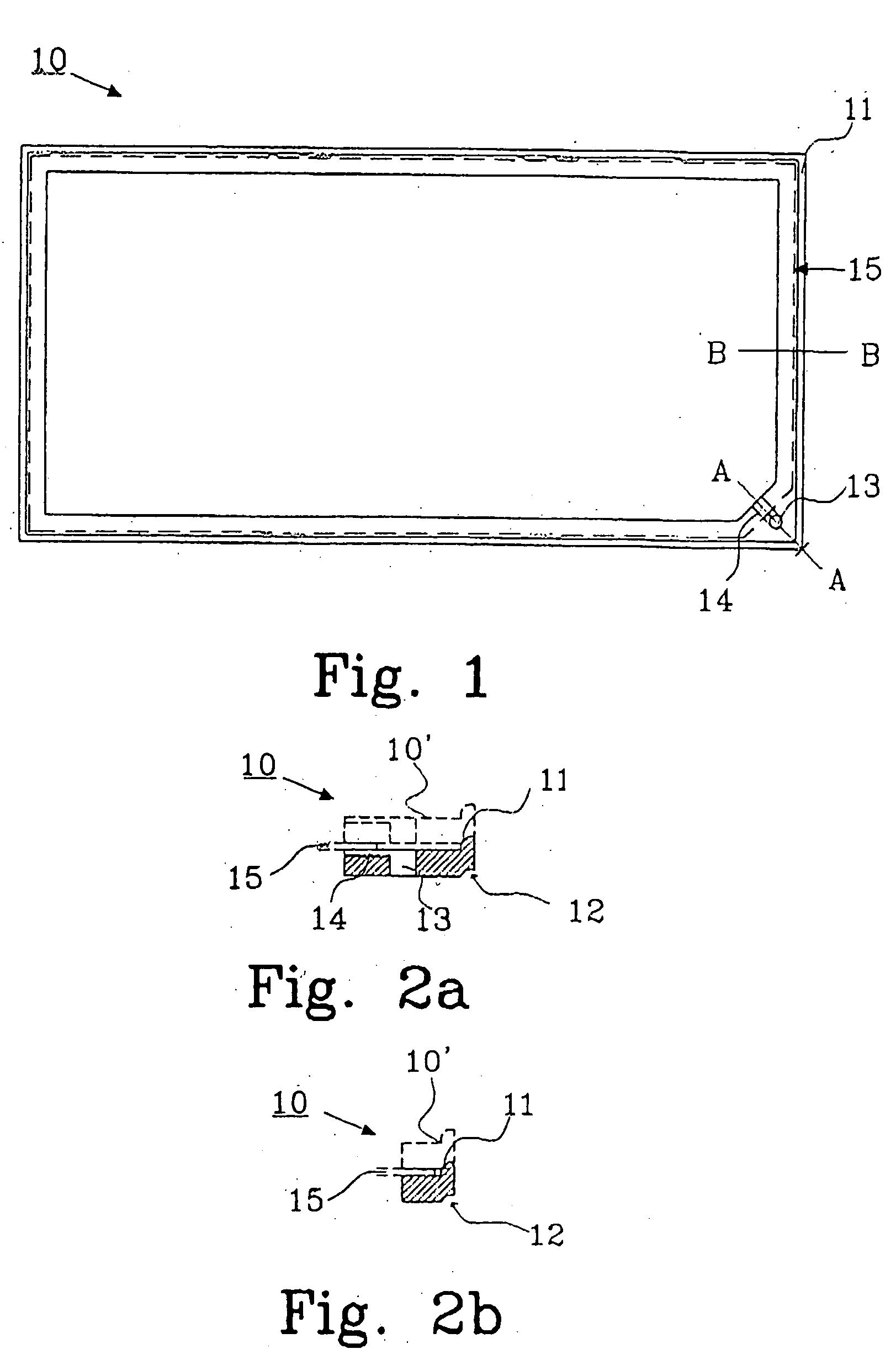
[0048]FIG. 1 shows a gasket 10 according to the invention. The gasket 10 is manufactured in a hydrophobic material having deformable properties, such as an elastomer or other material that create a continuous seal when deformed, to be able to function as a sealing. The gasket preferably has elastic properties, and a suitable material is a thermoplastic elastomer. Thermoplastic elastomers may be obtained from several manufacturers e.g. Engage® 8407 available from DuPont Dow Elastomers, DYNAFLEX® G2780-001 available from GLS Corp. or KRATON™ G-7705 available from Kraton™ Polymers. The gasket is preferably injection molded into the desired size and shape.

[0049] The gasket 10 is provided with a rim 11 at the edge on the upper side and a corresponding indentation 12 on the reverse side. The rim 11 and the indentation 12 will provide alignment of the gaskets when they are stacked upon each other in an assembled battery, see FIG. 7. The rim further serves to align the biplate relative to t...

second embodiment

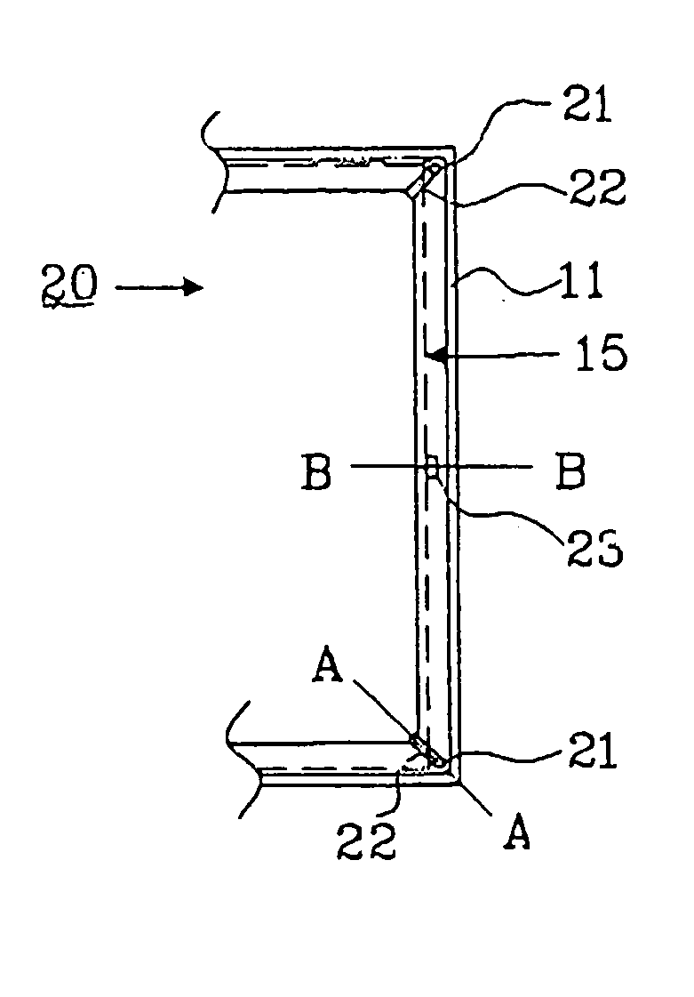
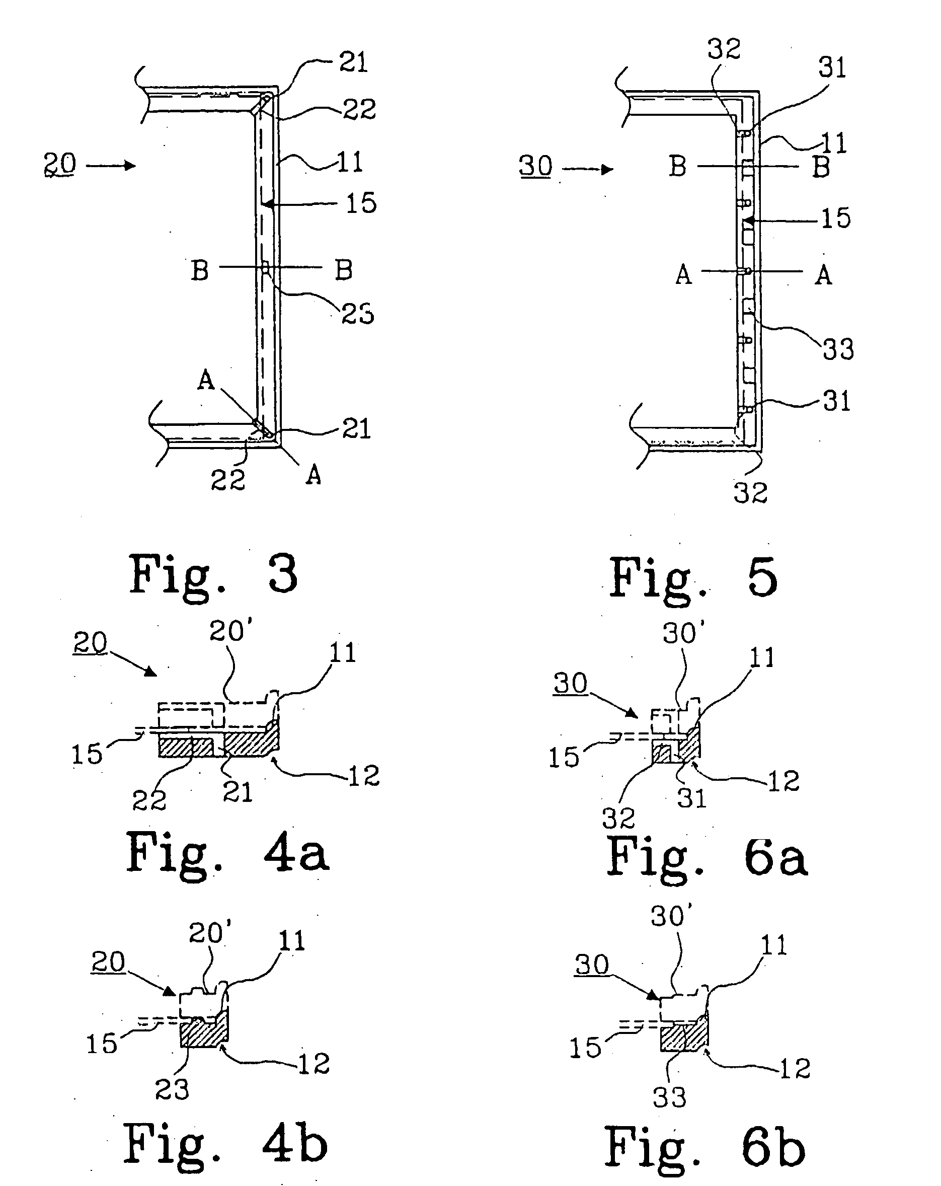
[0056]FIG. 3 shows a partial view of a gasket 20 according to the invention. The gasket 20 is provided with a rim 11 and a corresponding indentation 12, as described above. The gasket is provided with two rather small through-holes 21, each having a groove 22 to connect the through-hole 21 to the space inside the gasket as previously described in connection with FIG. 1. A biplate 15 is also shown with a dashed line to indicate the position of a biplate 15 in an assembled bipolar battery. To prevent the biplate to be misaligned during assembling of the battery, a guidance device 23, such as a boss, may be provided on the gasket 20. It should be noted that it is advantageous that the boss is designed in such a way that a passageway may be established between the two through-holes beside the biplate of each cell. In this embodiment the boss does not stretch all the way from the biplate to the rim.

[0057]FIG. 4a is a cross-sectional view along A-A in FIG. 3, and FIG. 4b is a cross-sectio...

third embodiment

[0058]FIG. 5 shows a partial view of a gasket 30 according to the invention. The gasket 30 is provided with a rim 11 and a corresponding indentation 12, as described above. The gasket is provided with five rather small through-holes 31, each having a groove 32 to connect the through-hole 31 to the space inside the gasket as previously described in connection with FIG. 1. A biplate 15 is also shown with a dashed line to indicate the position of a biplate 15 in an assembled bipolar battery. To prevent the biplate to be misaligned during assembling of the battery, several guidance devices 33, such as bosses, may be provided on the gasket 30. It should be noted that it is advantageous that the bosses are designed in such a way that a passageway may be established between the five through-holes beside the biplate of each cell. In this embodiment the bosses are lower than the thickness of the biplate.

[0059]FIG. 6a is a cross-sectional view along A-A in FIG. 5, and FIG. 6b is a cross-secti...


PUM

PropertyMeasurementUnit
Pressureaaaaaaaaaa
Elasticityaaaaaaaaaa
Hydrophobicityaaaaaaaaaa

Abstract

A gasket is for use in a starved electrolyte bipolar battery. The gasket may be made from a hydrophobic material in the shape of a frame to prevent the creation of an electrolyte path between adjacent cells when mounted in a battery. The frame may be designed to at least partially encompass a biplate when mounted in a bipolar battery, and include a device or way to permit gas passage through the gasket. The gasket may be made from a material with deformable properties to provide a sealing to a biplate and / or endplate when mounted in a bipolar battery, whereby an outer pressure tight seal of the battery may be obtained. A starved bipolar battery and a method for manufacturing a starved bipolar battery are also disclosed.

Description

TECHNICAL FIELD [0001] The present invention generally relates to a gasket, and / or to a bipolar battery including at least one gasket. The present invention also generally relates to a method for manufacturing a bipolar battery. BACKGROUND [0002] A bipolar battery construction includes an electrically conductive bipolar layer, so called biplate, that serves as electrical interconnection between adjacent cells in the battery as well as a partition between the cells. For efficient utilization of the bipolar construction, the biplate should be sufficiently conductive to transmit current from cell to cell, chemically stable in the cell's environment, capable of making and maintaining good contact to the electrodes and capable of being electrically insulated and sealable around the boundaries of the cell so as to contain electrolyte in the cell. [0003] The above is more difficult to achieve in rechargeable batteries due to the charging potential that can generate gas inside the battery, ...

Claims


Application Information

Patent Timeline
IPC IPC(8): H01M6/42H01M10/04H01M10/30H01M10/34H01M50/186H01M50/193H01M50/198H01M50/673
CPCH01M2/08Y10T29/49108H01M2/36H01M4/24H01M4/80H01M6/42H01M10/04H01M10/0418H01M10/044H01M10/282H01M10/287H01M10/30H01M10/345H01M10/347H01M2004/029Y02E60/124H01M2/12Y02E60/10H01M50/30Y02P70/50H01M50/673H01M50/186H01M50/193H01M50/198
Inventor PUESTER, NEIL H.HOCK, DAVIDFREDRIKSSON, LARS
Owner NILAR INT AB
Learn More