

Connector with built-in substrate and its assembling method
- Summary
- Abstract
- Description
- Claims
- Application Information
AI Technical Summary
Benefits of technology
Problems solved by technology
Method used
Image

Examples
Embodiment Construction
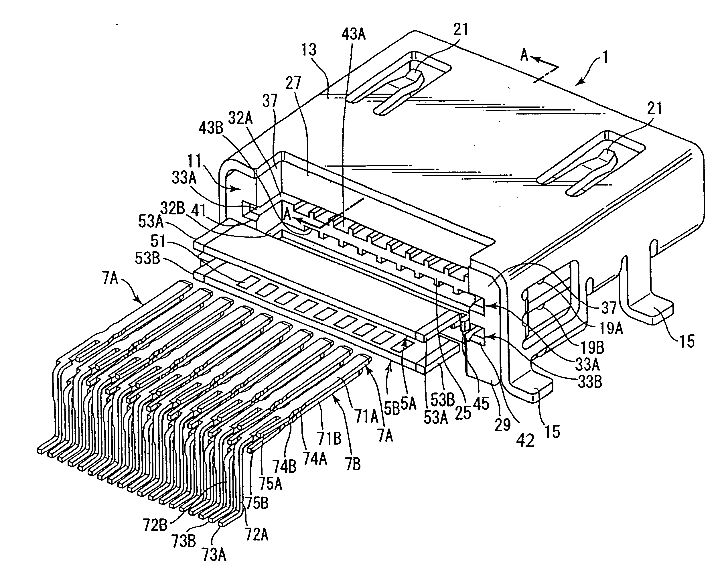
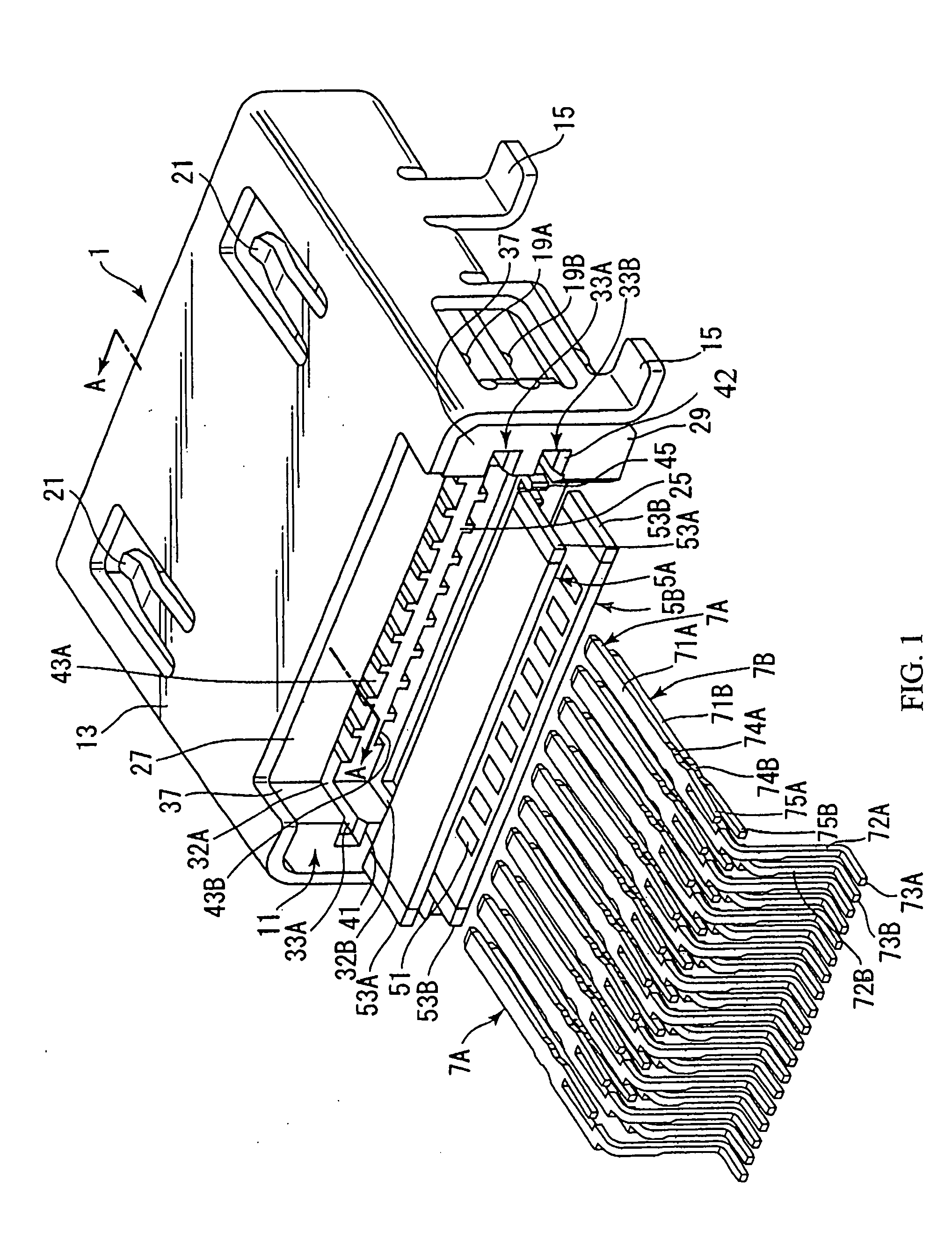
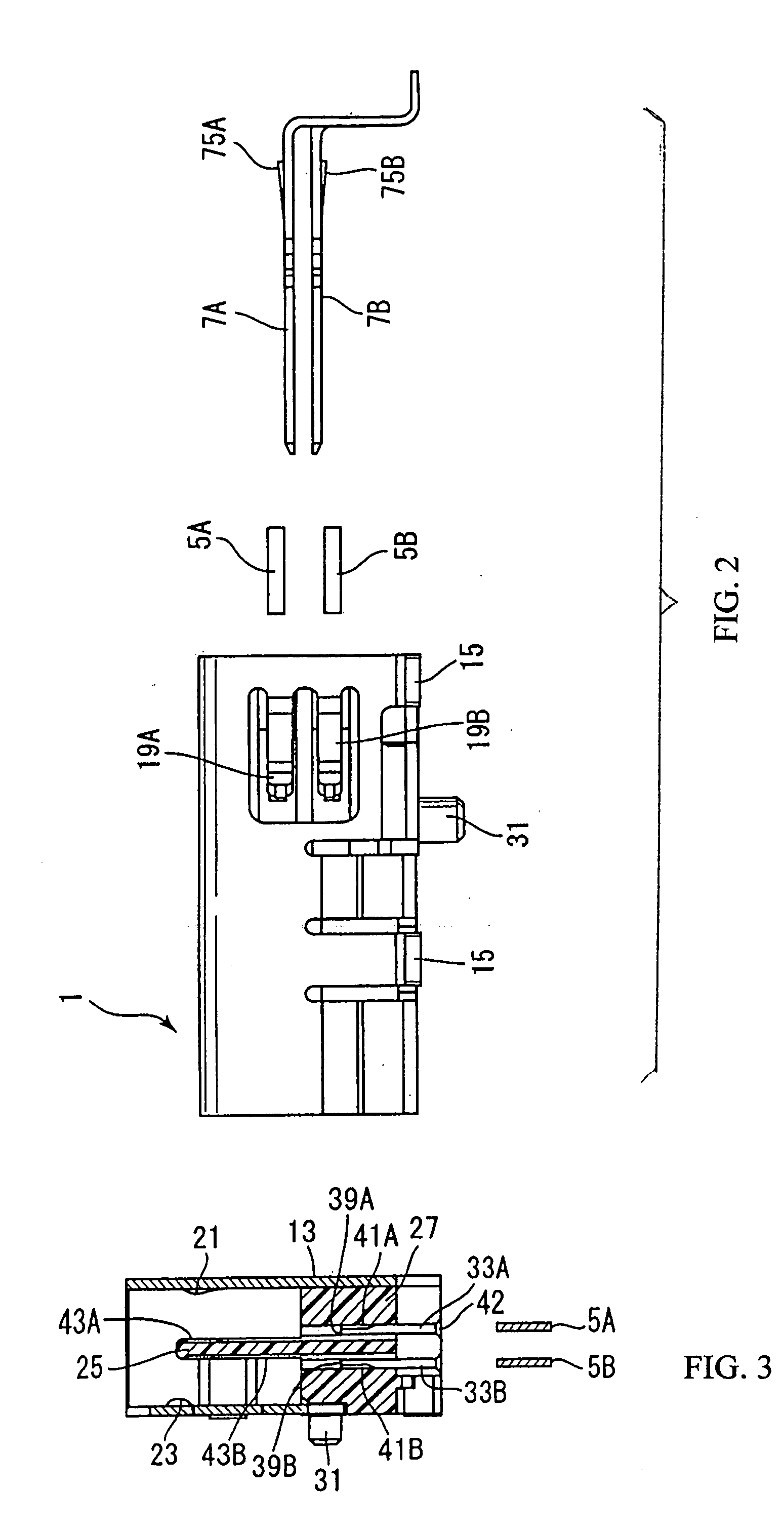
[0029] Embodiments of the invention will now be described with reference to the accompanying drawings. As a preferred embodiment of this invention, a connector with a built-in varistor, which has a varistor array (substrate) will be described as an example. The varistor array is formed so as to have a plurality of pads by printing metal patterns on a aluminum substrate. When current larger than specified amount flows to the pads, excess current flows outside by the varistor array. For example, if such connector with a built-in varistor is used in a mobile notebook computer or a cellular phone, which is easily touched by the user, it can be prevented that the internal IC is destroyed by undesired current, such as static electricity caused by the user.
[0030] Here, the connector with a built-in varistor described below shows an example of the connector with a built-in substrate of this invention. The connector with a built-in substrate of this invention can be applied for various conn...
PUM
 Abstract
Description
Claims
Application Information