Rolling tool and roller for rolling, particularly deep rolling, a work piece

a technology of rolling tool and roller, which is applied in the direction of metal rolling, manufacturing tools, grooves, etc., can solve the problems of minor wear caused directly to the roller, and achieve the effect of high quality and reproducibility of rolling operation, and extremely constant rolling for

Inactive Publication Date: 2005-05-19
ECOROLL WERKZEUGTECHN
View PDF9 Cites 34 Cited by
  • Summary
  • Abstract
  • Description
  • Claims
  • Application Information

AI Technical Summary

Benefits of technology

[0029] A roller with a spherical bearing of such shape is advantageous in that it may be pivoted absolutely neutrally and economically in terms of space.
[0030] The spherical shape even renders this roller accessible to a hydraulic, particularly hydrostatic bearing on the tool side to accommodate the roller. This enables the rolling force to be kept extremely constant, thereby assuring high quality and reproducibility of the rolling operation. Support is finally assured with the geometrically relatively simple form of a sphere and is thus independent of the conformation in the work piece contact area.

Problems solved by technology

As a result the degree of wear caused directly to the roller is minor.

Method used


Image

  • Rolling tool and roller for rolling, particularly deep rolling, a work piece
  • Rolling tool and roller for rolling, particularly deep rolling, a work piece
  • Rolling tool and roller for rolling, particularly deep rolling, a work piece

Examples


Embodiment Construction

[0048] Throughout all the Figures, same or corresponding elements are generally indicated by same reference numerals. These depicted embodiments are to be understood as illustrative of the invention and not as limiting in any way. It should also be understood that the drawings are not necessarily to scale and that the embodiments are sometimes illustrated by graphic symbols, phantom lines, diagrammatic representations and fragmentary views. In certain instances, details which are not necessary for an understanding of the present invention or which render other details difficult to perceive may have been omitted.

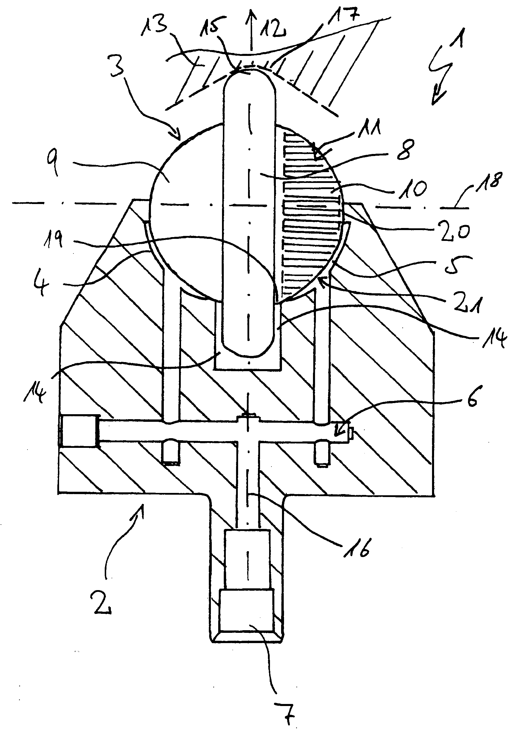
[0049] Rolling tool 1 in FIG. 1 essentially includes a roller cradle 2 and a roller 3. Roller 3 is supported by hydraulic bearings in roller cradle 2. For this, two hydraulic bearing pockets 4, 5 are used, which are supplied with a liquid during operation via a hydraulic feed system 6 in roller cradle 2. The liquid is forced on the tool side via a feed chamber 7 into roller ...


PUM

PropertyMeasurementUnit
radiiaaaaaaaaaa
areaaaaaaaaaaa
contact areaaaaaaaaaaa

Abstract

Previously known mechanical deep rolling tools share the feature that their rollers not only roll over the work piece but also over a counter roller on the tool side. This allows the deep rolling roller to swing to the side; but the roller material becomes fatigued relatively quickly. To achieve longer life, a rolling tool is suggested in which a working periphery is located in a work piece contact area spatially separated from a bearing contact area of the roller. A rolling tool with a hydraulically supported forming roller and a roller suitable therefor are also suggested.

Description

CROSS-REFERENCES TO RELATED APPLICATIONS [0001] This application is a continuation of prior filed copending PCT International application no. PCT / DE2004 / 001860, filed Aug. 20, 2004, which designated the United States and on which priority is claimed under 35 U.S.C. §120, the disclosure of which is hereby incorporated by reference, and which claims the priority of German Patent Application, Serial No. 103 40 267.5, filed Aug. 29, 2003, pursuant to 35 U.S.C. 119(a)-(d), the disclosure of which is incorporated herein by reference. [0002] This application also claims the benefit of prior filed U.S. provisional Application No. 60 / 506,749, filed Sep. 29, 2003, pursuant to 35 U.S.C. 119(e), the disclosure of which is incorporated herein by reference.BACKGROUND OF THE INVENTION [0003] The present invention relates to a rolling tool and a roller for rolling, particularly for deep rolling, a work piece. [0004] Nothing in the following discussion of the state of the art is to be construed as a...

Claims


Application Information

Patent Timeline
Patent Type & Authority Applications(United States)
IPC IPC(8): B23P9/02B24B39/00
CPCB21H7/185B24B39/003B23P9/02
Inventor OSTERTAG, ALFREDROTTGER, KARSTEN
Owner ECOROLL WERKZEUGTECHN
Why Eureka
Try Eureka