Artificial spinal disk

a technology of spinal discs and discs, applied in the field of artificial spinal disc designs, can solve the problems of difficult to effectively contain within the disk space, poor imitation of natural relative by coupling types, and risk of rupture or breakag

Inactive Publication Date: 2005-05-19
SMART DISC
View PDF7 Cites 202 Cited by
  • Summary
  • Abstract
  • Description
  • Claims
  • Application Information

AI Technical Summary

Benefits of technology

[0003] An artificial spinal disk comprises a central capsule that is configured to slide laterally within the disk space with one or more of flexion, extension, and lateral bending of the spine so as to shift an instantaneous center of rotation of the artificial disk. In one embodiment, the invention comprises an artificial spinal ...

Problems solved by technology

These designs provide flexibility, but present the risk of rupture or breakage, and can be difficult to contain effectively within the disk space.
However, these types of couplings do a poor job of imit...

Method used


Image

  • Artificial spinal disk
  • Artificial spinal disk
  • Artificial spinal disk

Examples


Embodiment Construction

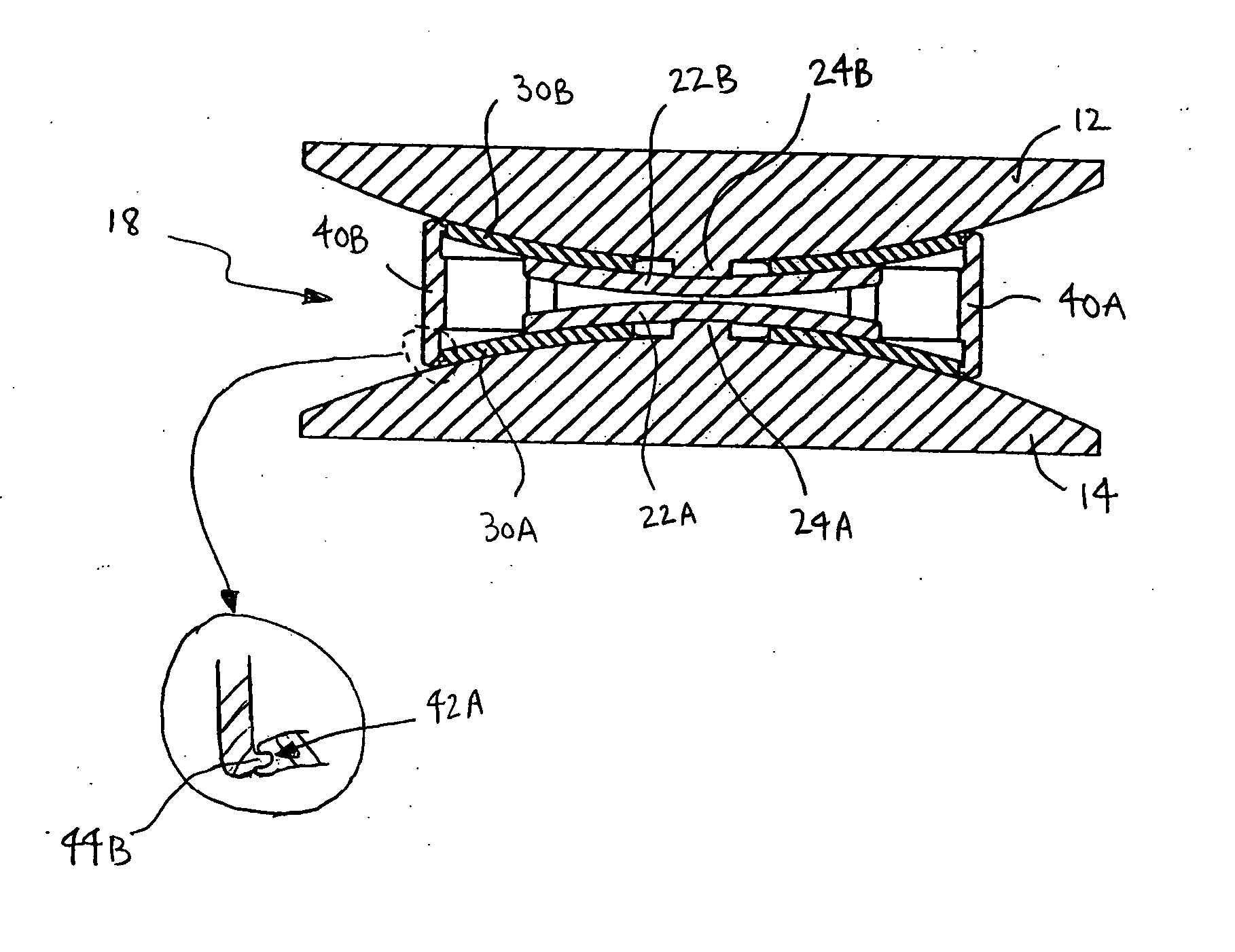
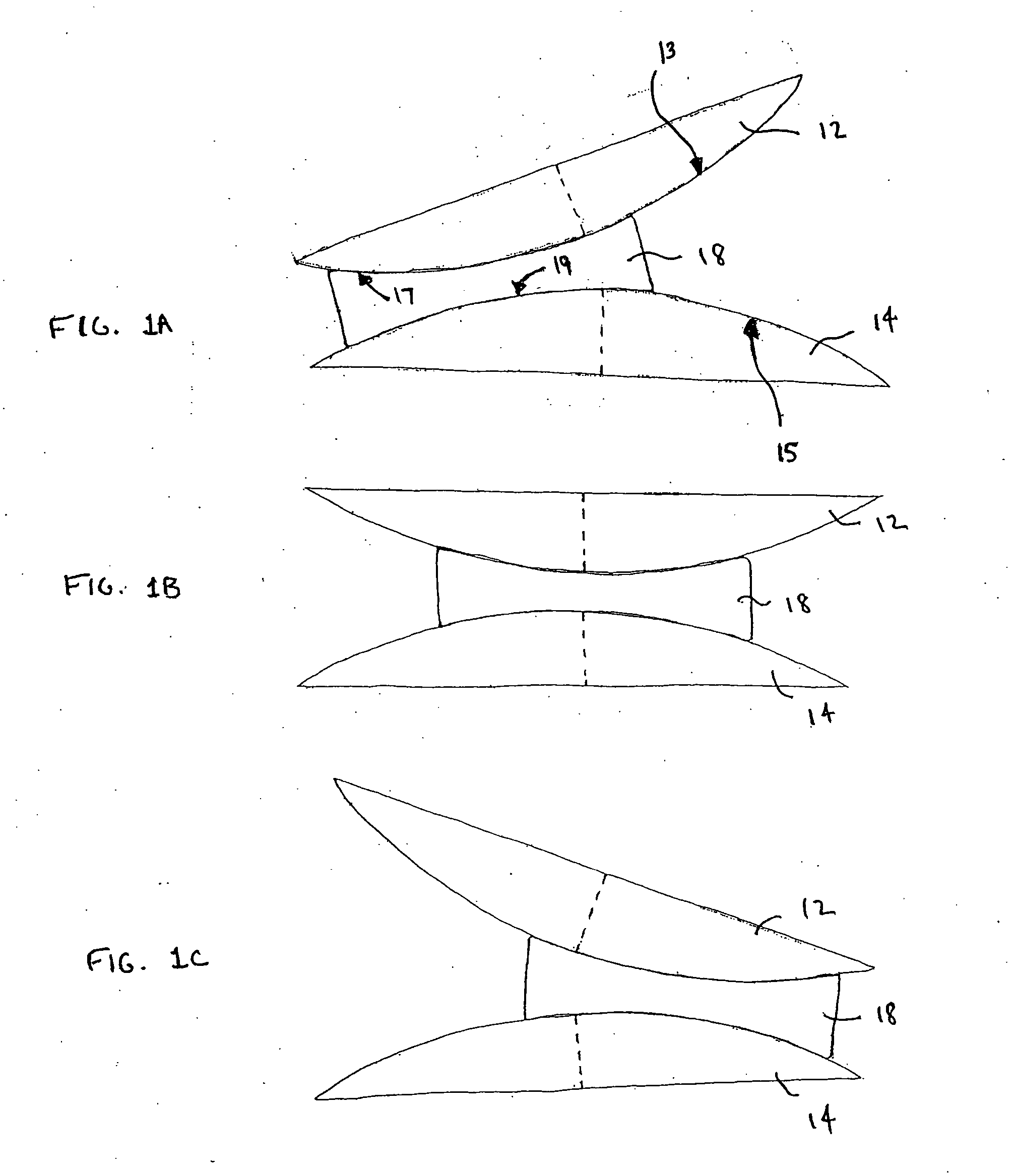
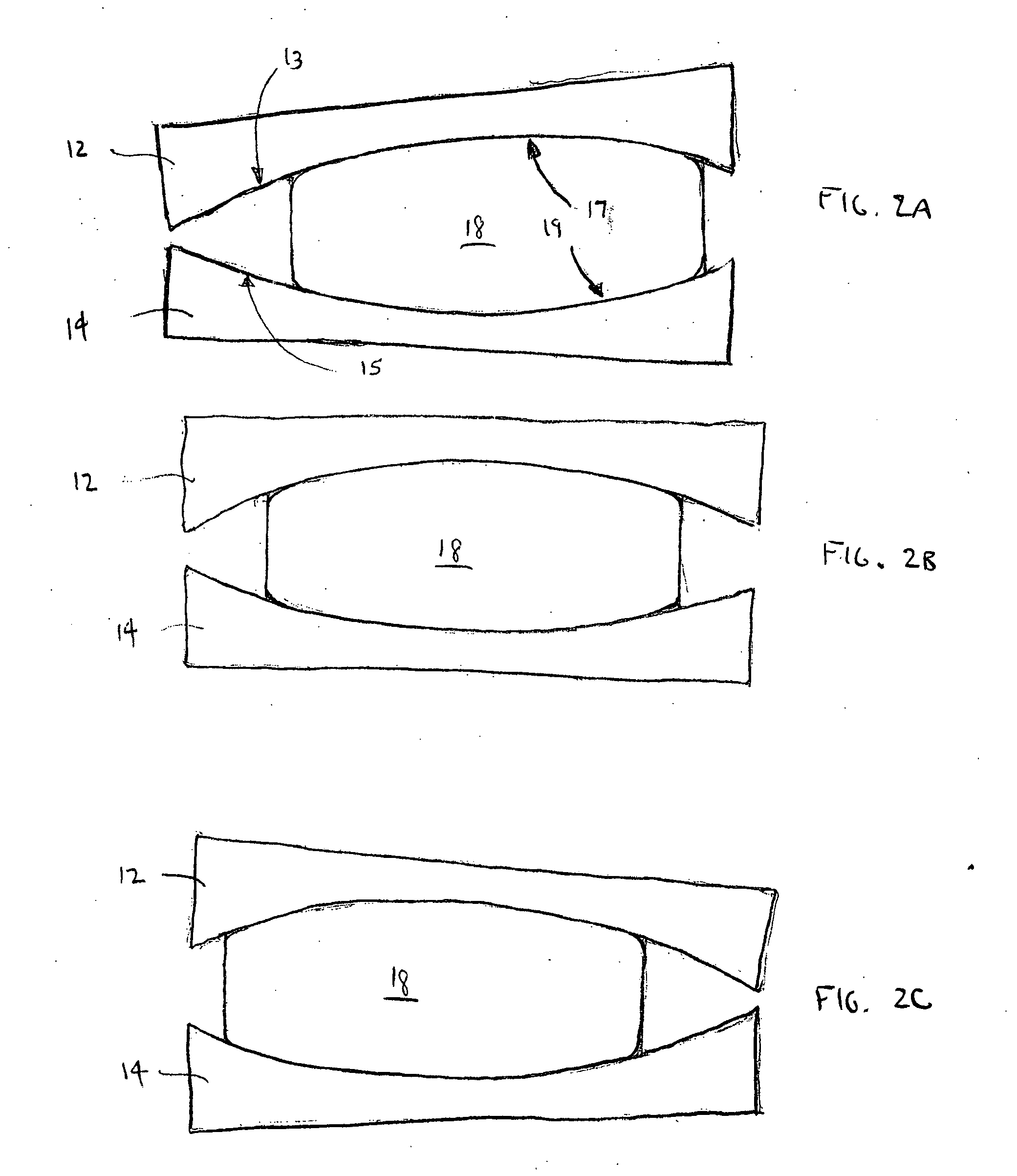
[0023] One embodiment of an artificial disk in accordance with the invention is shown in FIGS. 1A, 1B and 1C. In this embodiment, endplates 12, 14 sandwich a sliding central capsule 18. As shown in these Figures, a first plate 12 defines a first inwardly directed surface 13 and the second plate 14 defines a second inwardly directed surface 15. A central capsule 18 defines opposed outwardly directed surfaces 17, 19 that slidably mate with the inwardly directed surfaces of the plates. Thus, the central capsule can slide toward and away from opposed edge portions of the endplates as the relative endplate orientation changes during flexion, extension or lateral bending of the motion segment in which the artificial disk is installed. With this design, the endplates 12, 14 can also rotate with respect to one another as the central capsule slides between them. In this embodiment, the endplates have convex spherical contours, and the central capsule 18 is generally cylindrical with top and ...


PUM


Abstract

An artificial spinal disk comprises a central capsule that is configured to slide laterally within the disk space with one or more of flexion, extension, and lateral bending of the spine so as to shift an instantaneous center of rotation of the artificial disk. In one embodiment, the invention comprises an artificial spinal disk comprising a first plate having an inwardly directed surface, a second plate having an inwardly directed surface facing generally toward the inwardly directed surface of the first plate, and a central capsule with outwardly directed opposed faces that slidably mate with the inwardly directed surfaces of the first and second plates.

Description

CROSS REFERENCE TO RELATED APPLICATIONS [0001] This application claims priority under 35 U.S.C. Section 119(e) to U.S. Provisional Applications 60 / 467,655 filed on May 2, 2003 and 60 / 513,238 filed Oct. 21, 2003. The disclosures of both of these applications are hereby incorporated by reference in their entireties.BACKGROUND OF THE INVENTION [0002] A wide variety of artificial spinal disk designs have been developed over the past several years. Some designs, such as those described in U.S. Pat. Nos. 6,001,130 and 5,123,926 include resilient plastic or fluid filled bag type structures that are placed between adjacent vertebra. These designs provide flexibility, but present the risk of rupture or breakage, and can be difficult to contain effectively within the disk space. Other designs have attempted to use ball-and socket type couplers between endplates or other retaining devices attached to the vertebral bodies. Currently, devices which use metal-metal interfaces rather than resilien...

Claims


Application Information

Patent Timeline
IPC IPC(8): A61F2/00A61F2/28A61F2/30A61F2/44
CPCA61F2/4405A61F2310/0058A61F2/446A61F2002/2835A61F2002/30133A61F2002/30365A61F2002/30369A61F2002/30383A61F2002/30387A61F2002/30433A61F2002/30492A61F2002/30495A61F2002/305A61F2002/30507A61F2002/30517A61F2002/30579A61F2002/30599A61F2002/30604A61F2002/30662A61F2002/30663A61F2002/30685A61F2002/30841A61F2002/30884A61F2002/443A61F2220/0025A61F2220/0033A61F2220/0041A61F2230/0015A61F2250/0063A61F2310/00017A61F2310/00023A61F2/4425
Inventor ALLEYNE, NEVILLEGERCHOW, JAMES R.NONAKA, MAKOTOSLUDER, PHILIP JAMES
Owner SMART DISC
Why Eureka
Try Eureka