
Magnetic resonance imaging

Active Publication Date: 2017-02-21
FONAR
View PDF17 Cites 6 Cited by
  • Summary
  • Abstract
  • Description
  • Claims
  • Application Information

AI Technical Summary

Benefits of technology

The patent describes a method and apparatus for magnetic resonance imaging (MRI) that allows for better image quality and resolution. The method involves a variation signal that is used to randomize the orientations of nuclear spin axes within a specific zone. This results in signals emitted by nuclei outside of this zone that have a different phase than the signals emitted by Fig. 2 shows how this variation signal can be used to improve image quality and resolution in MRI. The technical effect is better and more accurate MRI data.

Problems solved by technology

Also, magnetic resonance imaging can obtain images of soft tissues and other features within the body which are not readily visualized using other imaging techniques.
However, the resulting MRI image may not be clear or free from artifacts.
For example, difficulties with the RF coils or the emitted magnetic field may produce artifacts in the resulting image (e.g., RF overflow artifacts, eddy current artifacts, zipper artifacts, etc.).
These artifacts may make the resulting image unclear or may lead a physician to an incorrect or uncertain diagnosis.

Method used


Image

  • Magnetic resonance imaging
  • Magnetic resonance imaging
  • Magnetic resonance imaging

Examples


Embodiment Construction

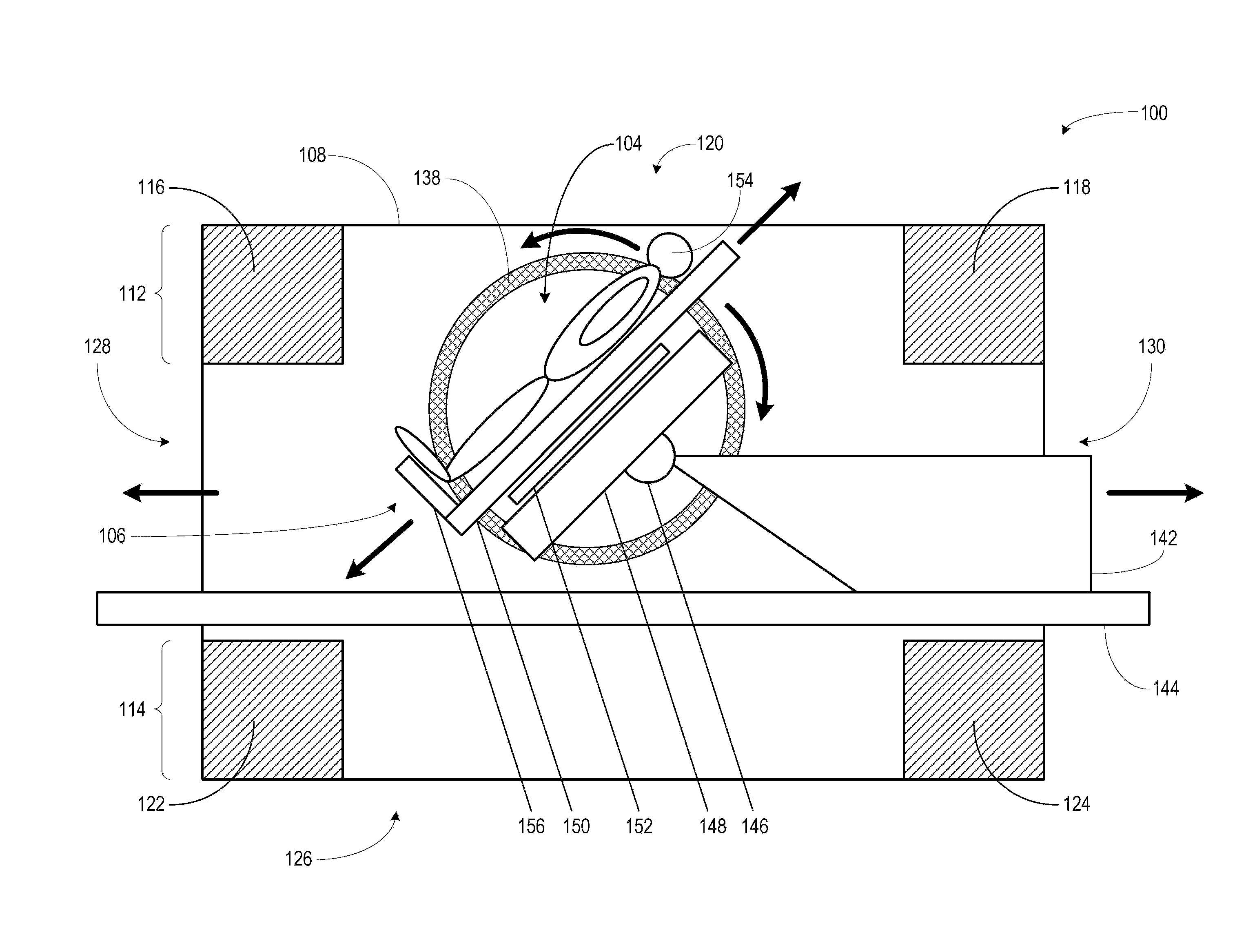
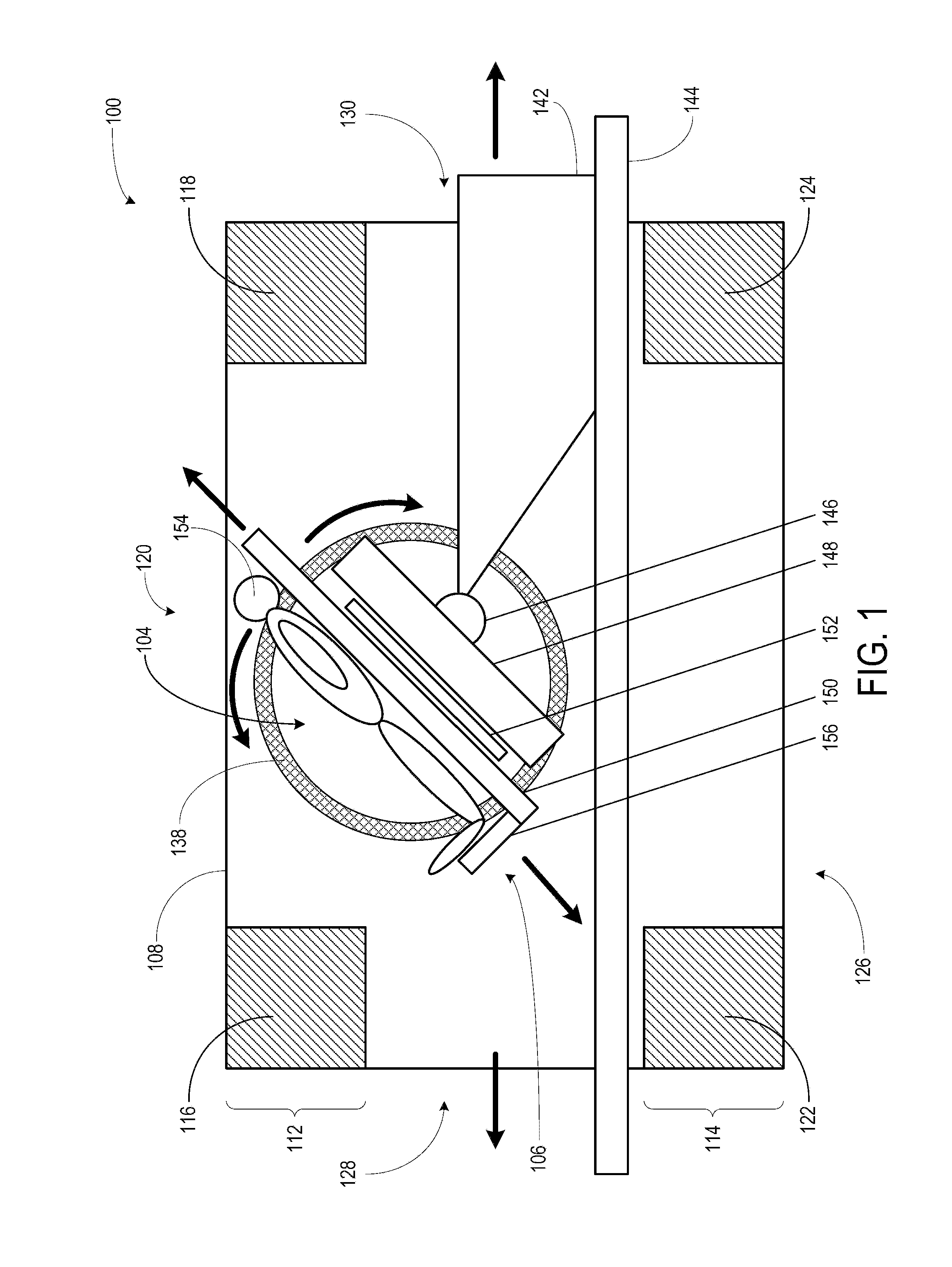
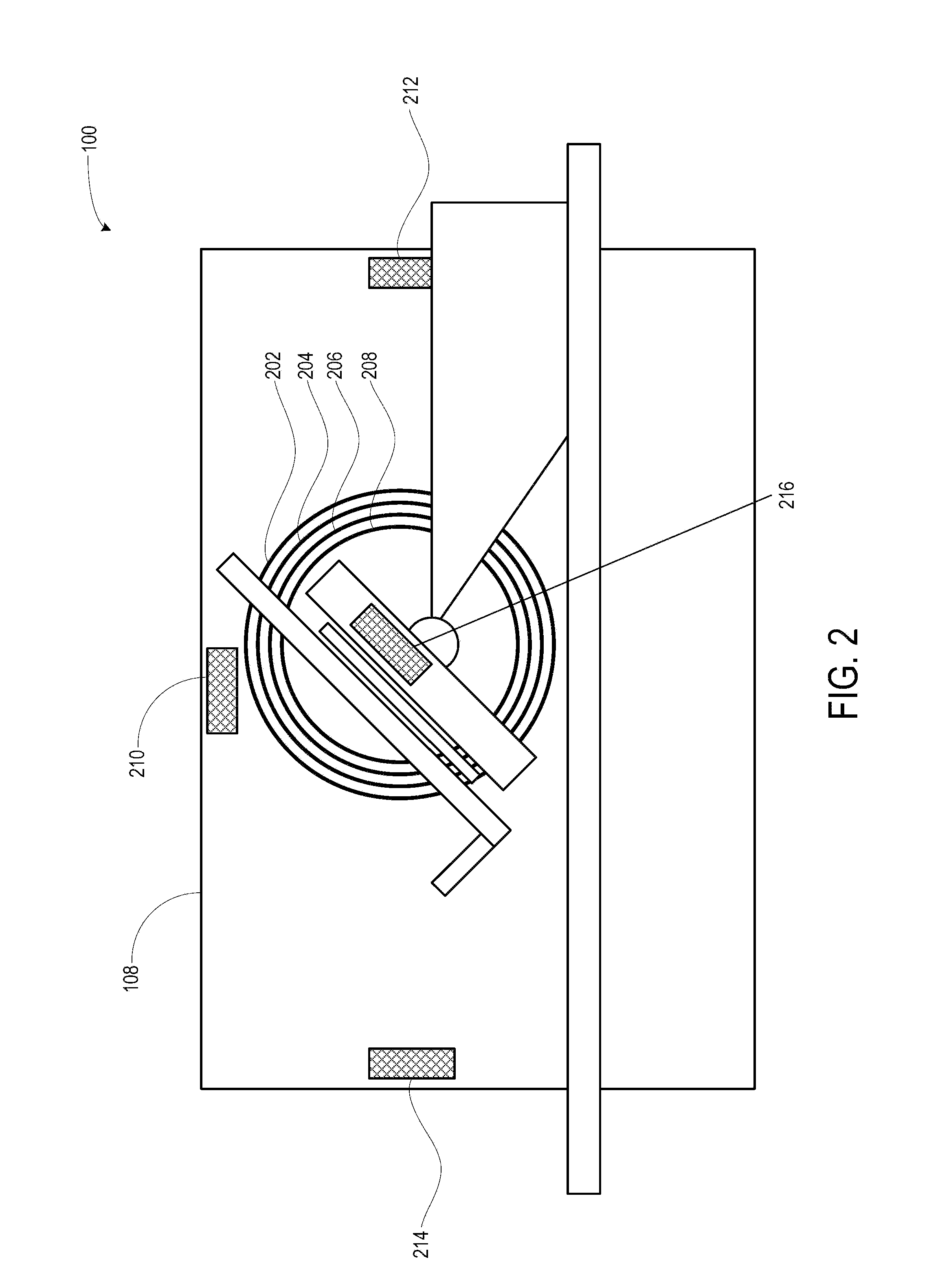
[0037]FIG. 1 shows a sectional view of an MRI apparatus 100. Emphasis in FIG. 1 is on the various assemblies relating to the generation of the magnetic field. FIG. 2, as discussed below, is directed to the radiofrequency coils used in the MRI apparatus 100 to image an object. The various assembles shown in FIG. 1 and FIG. 2 constitute the MRI apparatus 100.

[0038]In one embodiment, the MRI apparatus 100 includes a magnet having a ferromagnetic frame, a magnetic flux generator 104, and a patient handling system 106. The ferromagnetic frame includes a first side wall 108 and a second side wall (not shown). The side walls extend vertically. For purposes of clarity, FIG. 1 does not show the second side wall or any of its associated structures. The ferromagnetic frame also includes a top flux return structure 112 and a bottom flux return structure 114. The top flux return structure 112 may include two columnar structures 116 and 118. Between these two columnar structures, a top opening 12...


PUM


Abstract

An MRI apparatus employs a magnet for establishing a B0 field, one or more imaging radiofrequency coils for creating a B1 field, and one or more nulling radiofrequency coils. The RF energy emitted by the nulling radiofrequency coils may be configured such that it disrupts the nuclear magnetic resonance signals emitted by nuclei excited by the B1 field. In addition, the nulling radiofrequency coils may be calibrated to be 180° out of phase such that the RF energy emitted by a pair of nulling radiofrequency coils is cancelled at a location between them.

Description

CROSS-REFERENCE TO RELATED APPLICATIONS[0001]The present application claims the benefit of the filing date of U.S. Provisional Patent Application No. 61 / 775,610 filed Mar. 10, 2013, the disclosure of which is hereby incorporated herein by reference. The present application also claims the benefit of the filing date of U.S. Provisional Patent Application 61 / 775,614, filed Mar. 10, 2013, the disclosure of which is hereby incorporated herein by reference.TECHNICAL FIELD[0002]The present disclosure is generally directed to a magnetic resonance imaging (“MRI”) apparatus and method that includes radiofrequency (“RF”) scanning along a line between two RF coils. In particular, this disclosure provides for an MRI apparatus and method that incorporates one or more additional RF coils to create a null zone within an object being imaged to produce a more accurate and clear image.BACKGROUND[0003]In magnetic resonance imaging, an object to be imaged as, for example, a body of a human subject, is ...

Claims


Application Information

Patent Timeline
IPC IPC(8): G01R33/565
CPCG01R33/5659G01R33/307G01R33/36G01R33/4838
Inventor DAMADIAN, RAYMOND V.
Owner FONAR
Learn More