
Multi-Angle Seat For Antenna

a multi-angle seat and antenna technology, applied in the direction of collapsable antennas, resonant antennas, elongated active elements, etc., can solve the problems of antenna failure in a wide-angle shifting operation, the external joint cannot rotate in an angle of 180°, etc., to prevent the disruption of signal transmission lines resulting from an over-rotation of the sea

Inactive Publication Date: 2007-10-25
TYCO ELECTRONICS HLDG BERMUDA NO 7
View PDF3 Cites 4 Cited by
  • Summary
  • Abstract
  • Description
  • Claims
  • Application Information

AI Technical Summary

Benefits of technology

[0007]The tab of the seat is inserted in the first slot of the first socket and thereby a wide-angle rotation and shift thereof is achieved. Moreover, the protuberance of the first socket is inserted in the second slot of the second socket, and thereby the seat is driven by the first socket to rotate in a partial range of angle. Furthermore, since the two sides of the first slot are not connected with each other, the seat is able to be positioned after the wide-angle rotation, and the disruption of signal transmission lines resulting from an over-rotation of the seat is also thereby prevented.

Problems solved by technology

Nevertheless, while the antenna adapted to such a joint is rotated with the rotation thereof, the external joint can only rotate in an angle of 180°.
In this case, when such a joint is applied in the electronic application, the antenna may fail in a wide-angle shifting operation since the rotating angle thereof is limited.

Method used


Image

  • Multi-Angle Seat For Antenna
  • Multi-Angle Seat For Antenna
  • Multi-Angle Seat For Antenna

Examples


Embodiment Construction

[0014]The invention will now be described more specifically with reference to the following embodiments. It is to be noted that the following descriptions of embodiments of this invention are presented herein for the purpose of illustration and description only. They are not intended to be exhaustive or to be limited to the precise form disclosed.

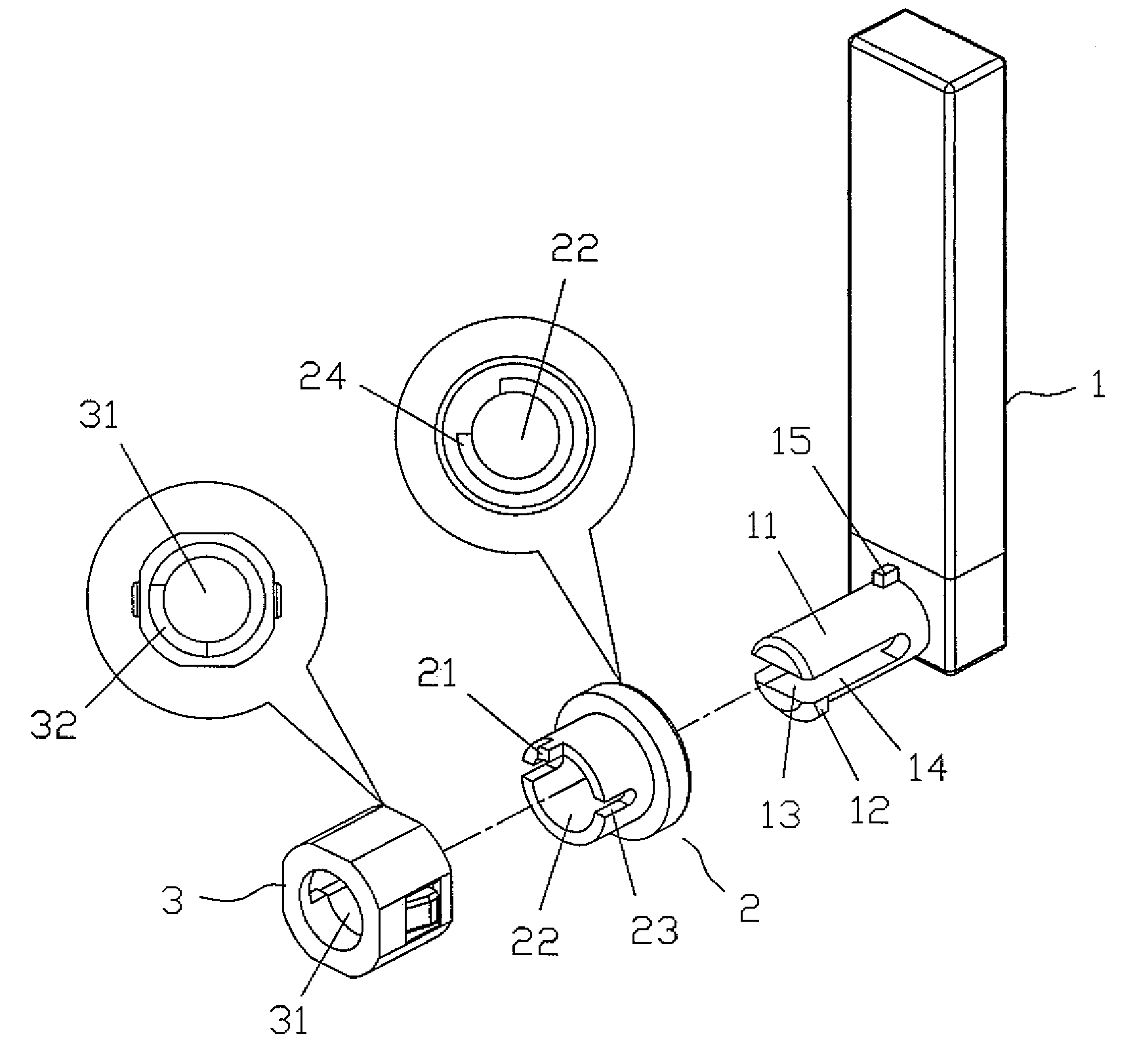
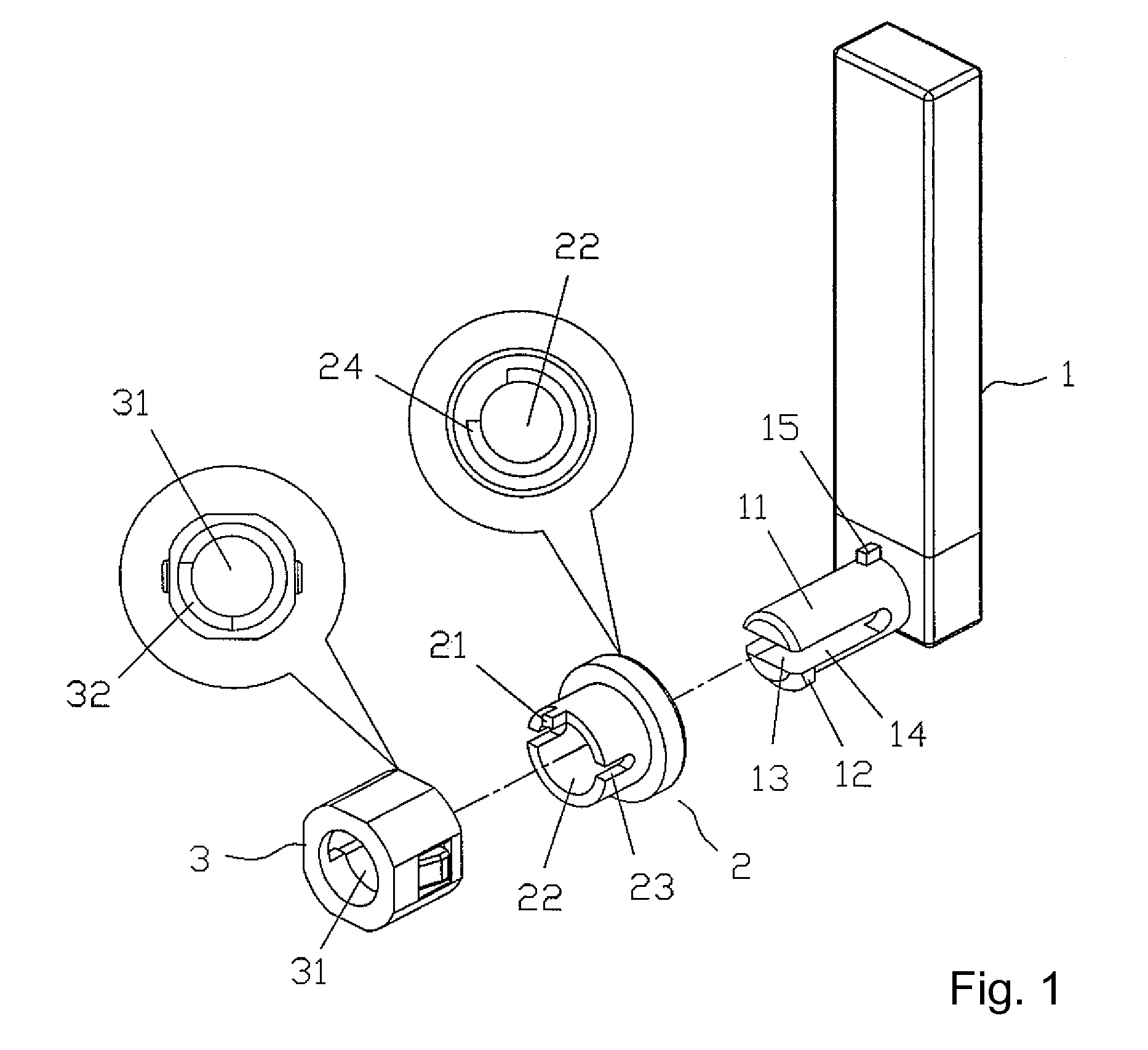
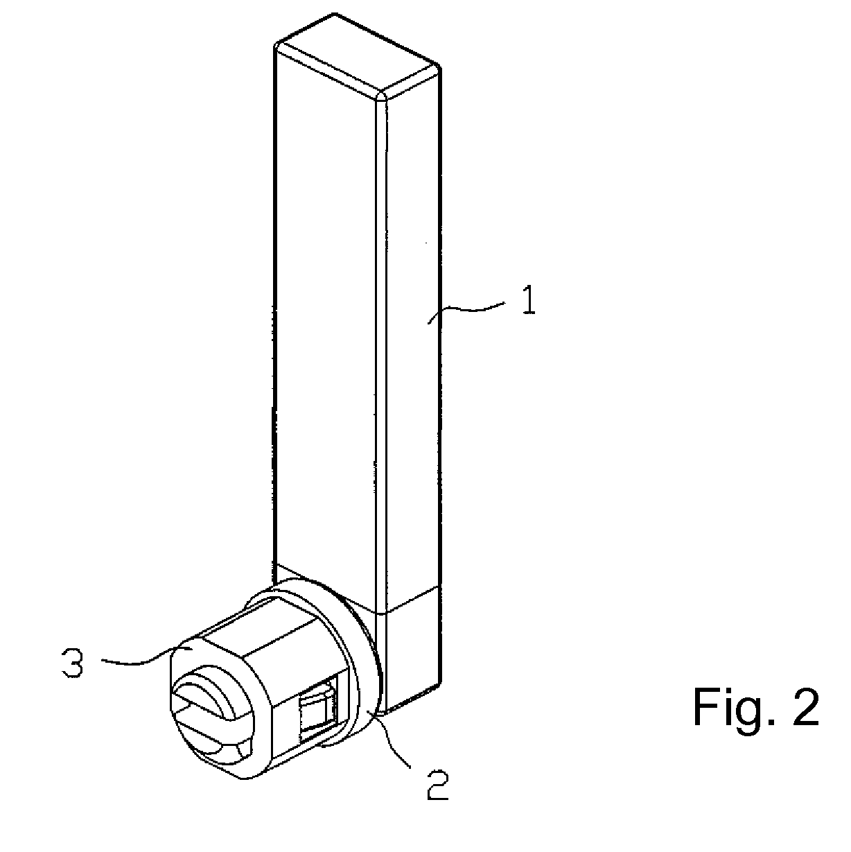
[0015]With reference to FIGS. 1 and 2, the multi-angle seat for antenna according to the embodiment shown mainly includes a seat 1 having a shaft 11 and a tab 15 configured thereon, a first socket 2 and a second socket 3. Referring to FIG. 3 as well, the tab 15 is inserted in the first slot 24 formed on the first socket 2, between the shaft 11 and the seat 1. The shaft 11 has a hollow portion 13 running therethrough and at least two grooves 14 formed thereon, so as to give the shaft 11 some resiliency. Moreover, on one end of the shaft 11, a fastener 12 is located. The shaft 11 passes through the hollow portion 22 of the first socket 2 and ...


PUM


Abstract

A wide-angle seat for an antenna includes a seat having a shaft and a tab located thereon, a first socket having a first slot on one end thereof and a protuberance on the other end thereof where the two sides of the first slot are not connected with each other, and a second socket having a second slot on one end thereof. The tab of the seat is inserted in the first slot of the first socket, and thereby a wide-angle rotation and shift thereof is achieved. Moreover, the protuberance of the first socket is inserted in the second slot of the second socket, and thereby the seat is driven by the first socket to rotate in a partial range of angle. Furthermore, since the two sides of the first slot are not connected with each other, the seat is able to be positioned after the wide-angle rotation, and the disruption of signal transmission lines resulting from an over-rotation of the seat is also prevented.

Description

CROSS-REFERENCE TO RELATED APPLICATIONS[0001]This application claims the benefit of the filing date under 35 U.S.C. § 119(a)-(d) of Taiwan, R.O.C. Patent Application No. 95206656, filed Apr. 19, 2006.FIELD OF THE INVENTION[0002]The present invention relates to a multi-angle seat for an antenna, and more particularly, to a multi-angle seat which enables a wide-angle rotation and prevents the disruption of signal transmission lines.BACKGROUND OF THE INVENTION[0003]In Taiwan Patent Pub. No. 534,465, a combination structure of the antenna rotating-positioning joint disclosed therein principally includes a protruding pillar for the right and the left slots on the seat for an external joint thereof, which are inserted in the through-holes on the connecting components of the seat for an internal joint thereof, and a positioning protruding piece inserted into a correspondent positioning slot. The protruding pillar serves as a rotation axis, and the seat for the external joint is accordingly...

Claims


Application Information

Patent Timeline
Patent Type & Authority Applications(United States)
IPC IPC(8): H01Q1/24
CPCH01Q9/30H01Q1/084
Inventor HUANG, TOMMY
Owner TYCO ELECTRONICS HLDG BERMUDA NO 7
Learn More