
Test socket which allows for ease of alignment

a test socket and socket technology, applied in the direction of coupling device connection, semiconductor/solid-state device testing/measurement, instruments, etc., can solve the problems of reduced overall space use efficiency, limited use of the test board space, etc., to reduce the overall current pass, prevent the reduction of signal transmission characteristics, and maximize the space utilization of the inspection apparatus

Active Publication Date: 2015-03-26
ISC CO LTD
View PDF3 Cites 7 Cited by
  • Summary
  • Abstract
  • Description
  • Claims
  • Application Information

AI Technical Summary

Benefits of technology

The present invention is a test socket that aims to maximize space utilization in an inspection apparatus and reduce signal transmission loss. It uses an elastic conductive sheet that is aligned by inserting conductive parts into an attachment on the inspection apparatus. Additionally, the test socket prevents reduction of signal transmission characteristics and reduces the overall current pass by allowing the elastic conductive sheet to directly contact the inspection apparatus. This simplifies the overall alignment structure and reduces inspection costs.

Problems solved by technology

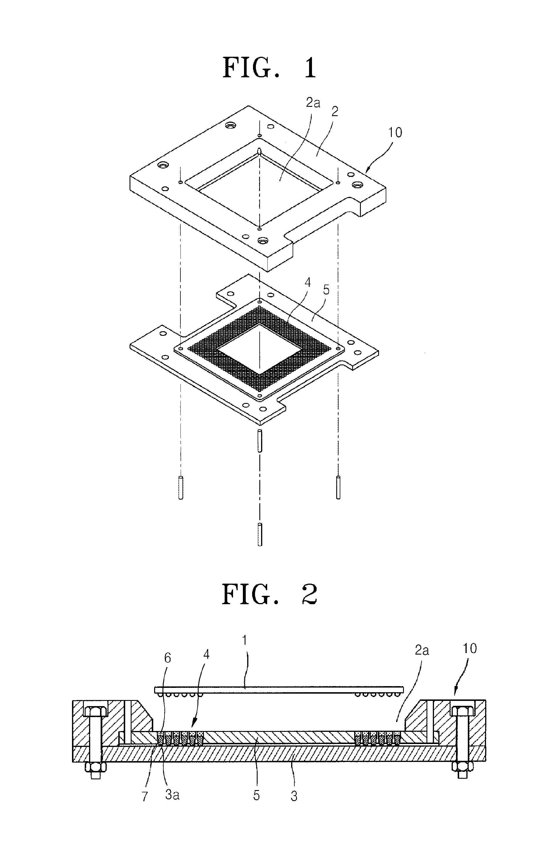
When the socket housing is used, sufficient use of a space around the test board is limited.
That is, a space of the test board on which the socket housing is seated is not used, thereby reducing the overall space use efficiency.
The test socket according to the conventional technology has also a problem in that use of a space of the test board is limited due to the base cover that is seated on the test board.
That is, a space occupied by the base cover is not sufficiently used, thereby reducing the overall space use efficiency.
In this case, the test board may be damaged.
Since the test board is more expensive than the test socket, when the test board is damaged, costs for replacing the test board are excessively high.

Method used


Image

  • Test socket which allows for ease of alignment
  • Test socket which allows for ease of alignment
  • Test socket which allows for ease of alignment

Examples


Embodiment Construction

Technical Problem

[0015]In order to solve the afore-described problems, the present invention provides a test socket that maximizes space utilization of an inspection apparatus, improves the overall signal transmission characteristics, and is easily manufactured.

Technical Solution

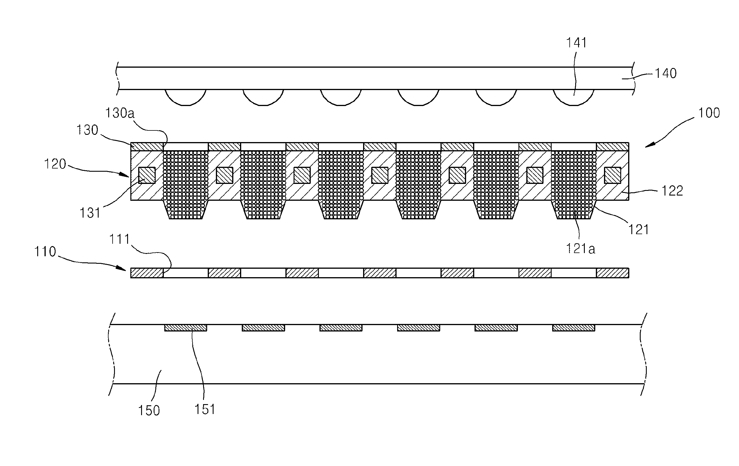
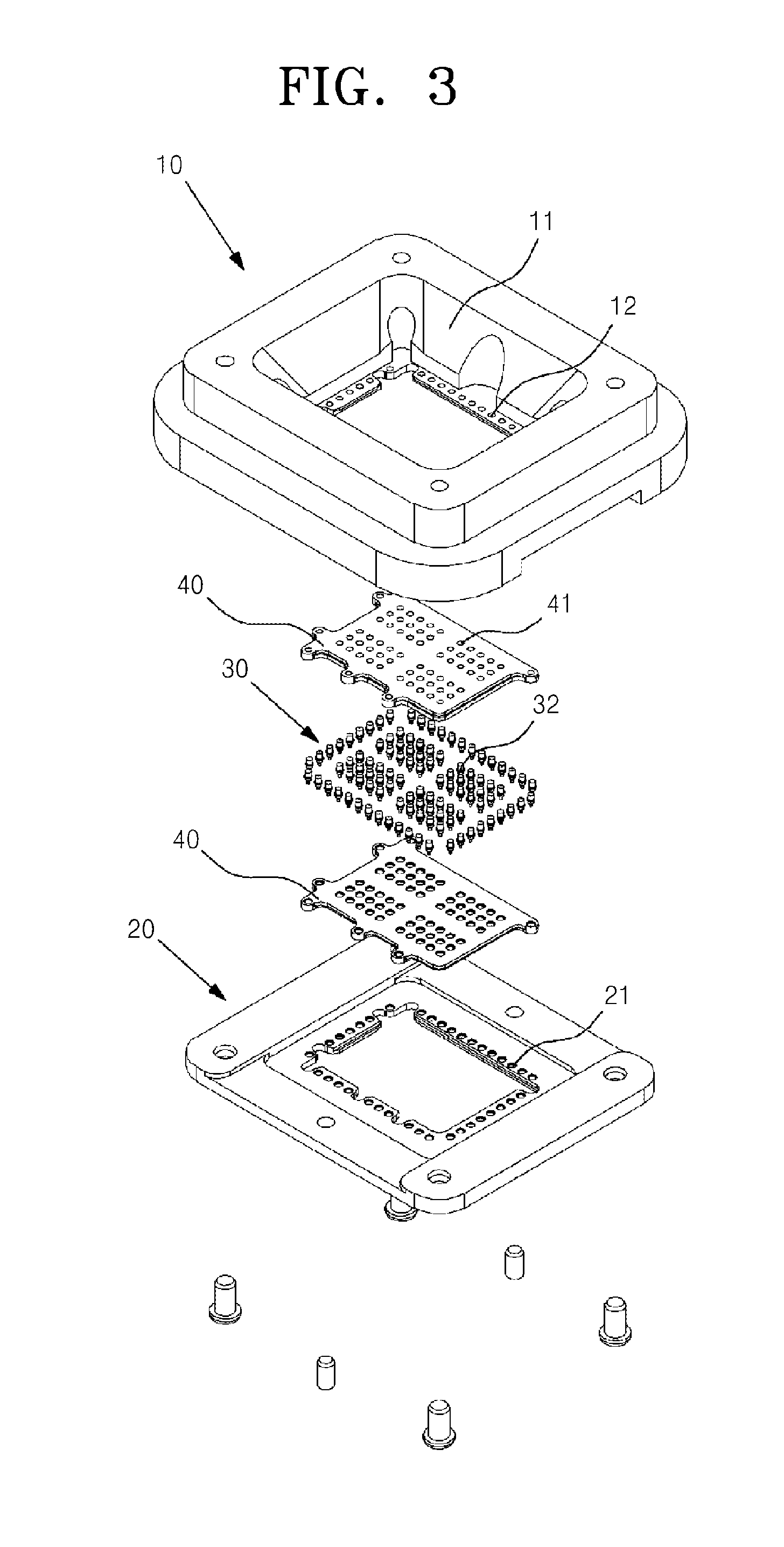
[0016]According to an aspect of the present invention, there is provided a test socket that is interposed between a device to be inspected and an inspection apparatus so as to electrically connect terminals of the device to be inspected and pads of the inspection apparatus, the test socket including: an alignment member that has a plurality of through-holes formed at points corresponding to the terminals of the device to be inspected or the pads of the inspection apparatus and is attached to the inspection apparatus such that the through-holes are located at the pads of the inspection apparatus; and an elastic conductive sheet including conductive parts that are disposed at the points corresponding to the te...


PUM


Abstract

The present invention relates to a test socket which allows for ease of alignment, and more particularly, to a test socket that is interposed between a device to be inspected and an inspection apparatus so as to electrically connect terminals of the device to be inspected and pads of the inspection apparatus, the test socket including: an alignment member that has a plurality of through-holes formed at points corresponding to the terminals of the device to be inspected or the pads of the inspection apparatus and is attached to the inspection apparatus such that the through-holes are located at the pads of the inspection apparatus; and an elastic conductive sheet including conductive parts that are disposed at the points corresponding to the terminals of the device to be inspected and include a plurality of conductive particles that are distributed in an insulating elastic material, insulating support parts that support the conductive parts and disconnect an electrical connection between adjacent conductive parts, and protruding conductive parts that protrude downward from the conductive parts and are inserted into the plurality of through-holes of the alignment member, wherein when the protruding conductive parts are inserted into the through-holes of the alignment member, the elastic conductive sheet is aligned in the the alignment member.

Description

TECHNICAL FIELD[0001]The present invention relates to a test socket which allows for ease of alignment, and more particularly, to a test socket which allows for ease of alignment so that space efficiency may be maximized and easy alignment may be performed.BACKGROUND ART[0002]In general, in order to inspect the electrical properties of a device, the device has to be stably electrically connected to a test apparatus. In general, a test socket is used as a tool for electrically connecting the device and the test apparatus.[0003]The test socket is used to connect terminals of the device and pads of the test is apparatus and enable electrical signals to be exchanged between the device and the test apparatus. For this purpose, the test socket includes an elastic conductive sheet or a pogo pin as a connection medium. The elastic conductive sheet that connects elastic conductive parts to the terminals of the device to be inspected and the pogo pin that includes a spring therein are used in...

Claims


Application Information

Patent Timeline
Patent Type & Authority Applications(United States)
IPC IPC(8): G01R1/04G01R31/28H01R33/76G01R31/26H01L21/66
CPCG01R31/28G01R1/0416H01R12/714H01R12/73H01R13/2414H01R13/2421H01R2201/20G01R1/0466G01R1/0483H01R33/76G01R31/26H01L22/00
Inventor LEE, JAE HAK
Owner ISC CO LTD
Learn More