Battery pack mounting structure of vehicle

a technology for mounting structures and batteries, applied in the direction of battery/fuel cell control arrangement, cell components, propulsion by batteries/cells, etc., can solve the problem of significant weight of battery packs, achieve the effect of minimizing modification of existing vehicle structures, maximizing spatial utilization within vehicles, and minimizing us

Active Publication Date: 2014-07-08
HYUNDAI MOTOR CO LTD +1
View PDF15 Cites 13 Cited by
  • Summary
  • Abstract
  • Description
  • Claims
  • Application Information

AI Technical Summary

Benefits of technology

[0008]The present invention has been made in an effort to provide a battery pack mounting structure of a vehicle configured to minimize modification of an existing vehicle structure and maximize spatial utilization within the vehicle by minimizing the use by the battery pack mounting structure of existing effective indoor space or a trunk compartment, provide excellent mounting workability of the battery pack, uniformly cool each of the battery cells constituting the battery pack, and prevent occupants from being exposed to an uncomfortable air flow environment by discharging air cooling a battery to the outside.

Problems solved by technology

Since the volume of the battery pack is quite significant, providing an appropriate mounting space within a vehicle is one of the primary technological issues faced by vehicle manufactures.
Further, since the weight of the battery pack is significant, ensuring workability within a mounting operation is also a concern.

Method used


Image

  • Battery pack mounting structure of vehicle
  • Battery pack mounting structure of vehicle
  • Battery pack mounting structure of vehicle

Examples


Embodiment Construction

[0020]First, it is understood that the term “vehicle” or “vehicular” or other similar term as used herein is inclusive of motor vehicles in general such as passenger automobiles including sports utility vehicles (SUV), buses, trucks, various commercial vehicles, watercraft including a variety of boats and ships, aircraft, and the like, and includes hybrid vehicles, electric vehicles, plug-in hybrid electric vehicles, hydrogen-powered vehicles and other alternative fuel vehicles (e.g. fuels derived from resources other than petroleum). As referred to herein, a hybrid vehicle is a vehicle that has two or more sources of power, for example both gasoline-powered and electric-powered vehicles.

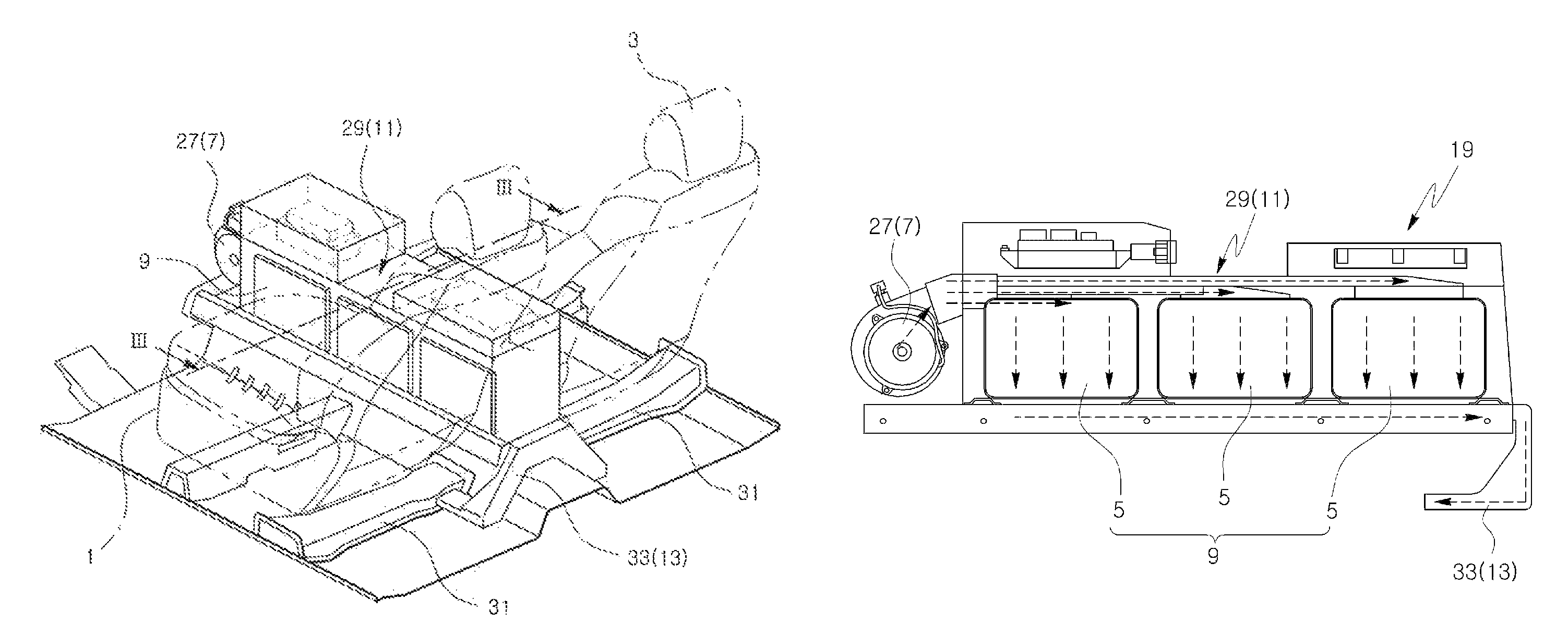
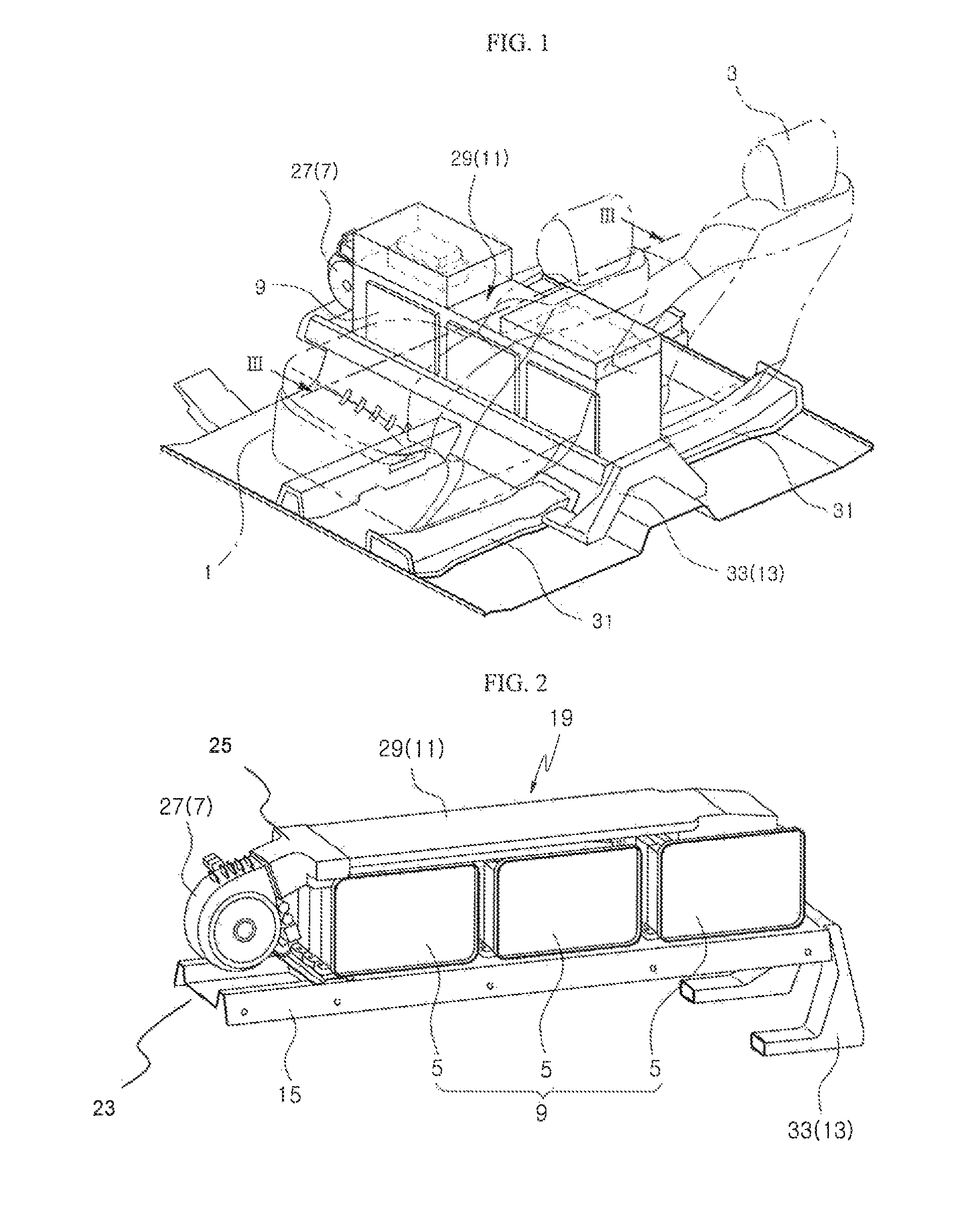
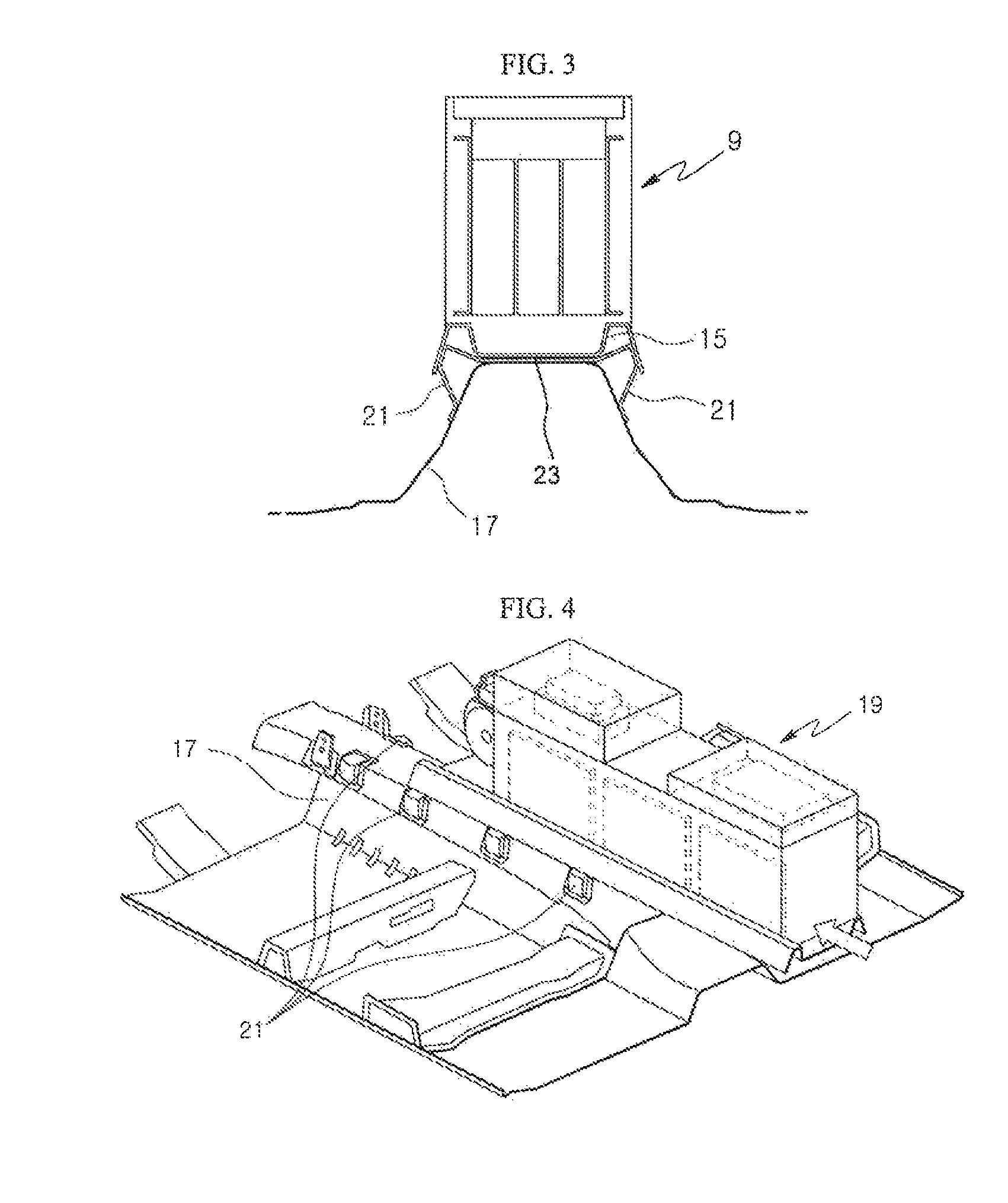
[0021]Referring to FIGS. 1 to 8, a battery pack mounting structure of a vehicle according to an exemplary embodiment of the present invention includes a battery pack 5 mounted lengthwise in a center console installation space between a driver seat 1 and a passenger seat 3, a cooling air providing me...


PUM

PropertyMeasurementUnit
rotational forceaaaaaaaaaa
shapeaaaaaaaaaa
voltageaaaaaaaaaa

Abstract

Disclosed is battery pack mounting structure for a high capacity battery in a vehicle. More specifically, a battery pack that includes a plurality of modules is mounted lengthwise in a center console installation space between a driver seat and a passenger seat. A cooling air providing means is configured to supply cooling air to a front protion of the battery pack, and a cooling air distributing means is configured to distribute the cooling air provided by the cooling air providing means to each of a plurality of battery modules individually. Finally, a discharge duct means is configured to receive cooling air that has already passed over each of the individual battery modules and discharge the cooling air through a rear portion of the battery pack to outside of a vehicle body.

Description

CROSS-REFERENCE TO RELATED APPLICATION[0001]This application claims under 35 U.S.C. §119(a) the benefit of Korean Patent Application No. 10-2011-0127773 filed on Dec. 1, 2011, the entire contents of which are incorporated herein by reference.BACKGROUND[0002](a) Technical Field[0003]The present invention relates to a battery pack mounting structure of a vehicle, and more particularly, to a structure configured to mount a high voltage battery pack within a hybrid vehicle or an electric vehicle while providing a cooling structure thereof.[0004](b) Background Art[0005]A high voltage battery pack capable of supplying a large amount of electricity is typically mounted in a hybrid vehicle or an electric vehicle. Since the volume of the battery pack is quite significant, providing an appropriate mounting space within a vehicle is one of the primary technological issues faced by vehicle manufactures. Further, since the weight of the battery pack is significant, ensuring workability within a ...

Claims


Application Information

Patent Timeline
Patent Type & Authority Patents(United States)
IPC IPC(8): B60K1/04H01M50/204H01M50/244H01M50/249
CPCH01M2/1083H01M10/5073B60K11/06H01M10/5067H01M10/5016B60K1/04H01M10/5004H01M10/5032B60K2001/0427B60K2001/005H01M10/647H01M10/6563Y02E60/12H01M10/613H01M10/625H01M10/6566Y02E60/10Y02T10/70H01M50/204H01M50/249H01M50/244B60L58/26B60L50/66B60L50/64B60Y2400/89B60Y2200/92B60Y2200/91
Inventor LIM, HAE KYUJEON, YOON CHEOLLEE
Owner HYUNDAI MOTOR CO LTD
Why Eureka
Try Eureka