Grid midsole insert

Inactive Publication Date: 2005-05-26
SAUCONY
View PDF43 Cites 130 Cited by
  • Summary
  • Abstract
  • Description
  • Claims
  • Application Information

AI Technical Summary

Benefits of technology

[0009] In one embodiment, a midsole insert for a shoe is provided. The midsole insert includes a body having a heel portion, a midfoot portion, and a forefoot portion, and a plurality of grid systems located on the midsole insert. Each grid s

Problems solved by technology

Mesh used in that construction, however, provided only stiffness and wearing qualities at the bottom of the heel.
That patent failed to

Method used


Image

  • Grid midsole insert
  • Grid midsole insert
  • Grid midsole insert

Examples


Embodiment Construction

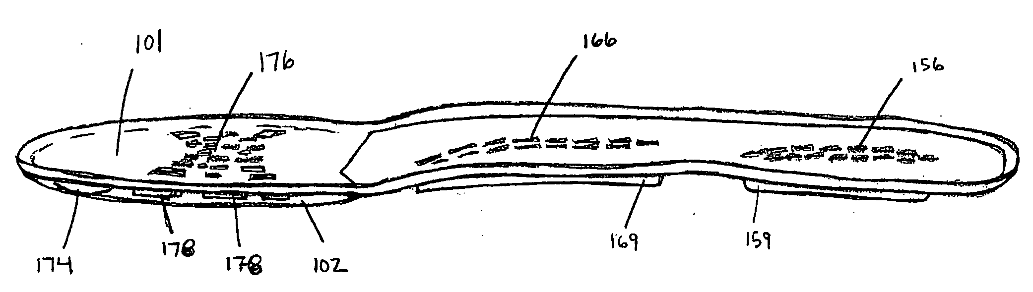
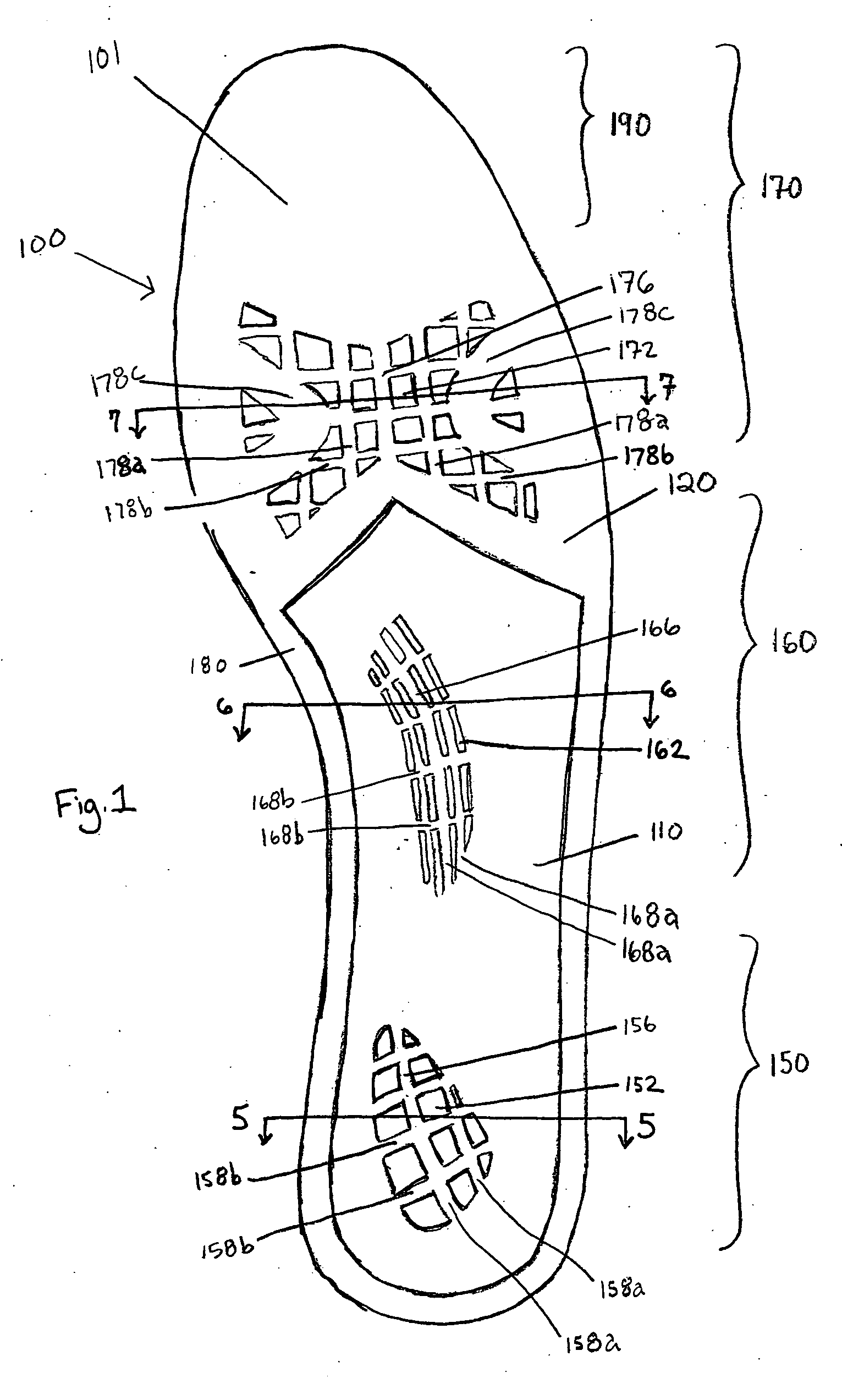
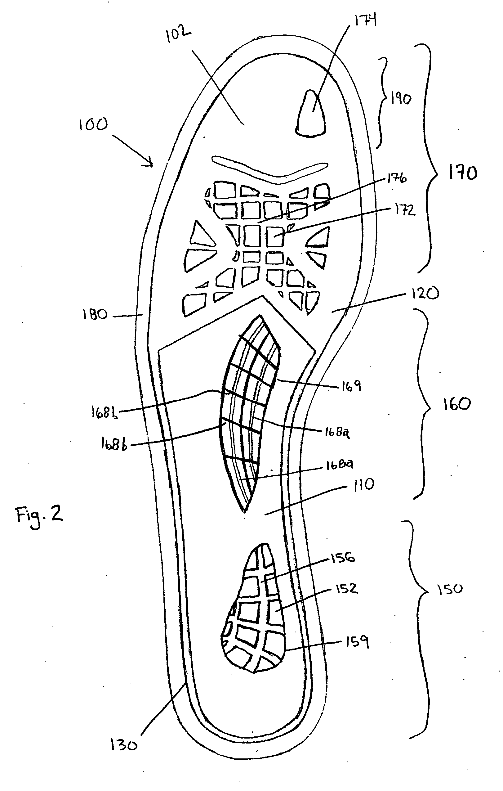
[0022] Aspects of the invention are directed to a midsole insert having energy return grid systems incorporated into the midsole insert itself. The energy return system of the present invention includes the use of components in the midsole region that provide both cushioning and energy return characteristics. These components may be selectively employed in the heel, midfoot, and / or the forefoot portions to provide the desired energy return characteristics for a particular type of shoe. These components may be especially designed for use in walking shoes or specific types of athletic shoes, such as basketball or running shoes. Further, the design of the midsole insert is a full footed design supporting the entire bottom of the wearer's foot. In one embodiment, the midsole insert is a single molded design featuring the grid energy return technology to address all phases of the gait cycle, and this new design replaces conventional running shoe designs which feature several components o...


PUM


Abstract

A midsole insert for use with a shoe is provided. The midsole insert includes a heel portion, a midfoot portion, and a forefoot portion, and a plurality of grid systems located on the midsole insert, where each grid system includes a plurality of openings cut into the midsole insert forming a lattice pattern. The plurality of grids may be located on at least one of the heel portion, the midfoot portion, and the forefoot portion, constructed to provide energy return features. The midsole may further be constructed and arranged to attach directly to an upper during a manufacturing step, to secure the shape of the upper on a last. By attaching directly to the upper, the midsole insert eliminates the need for a stroble board, which is typically used to secure the upper to the last. By eliminating the stroble board, the present invention places the midsole insert and the energy return grid system closer to the foot, which maximizes reaction time and performance. The midsole insert may be formed of at least two materials having different hardnesses, such that the heel portion has a greater hardness than the forefoot portion.

Description

FIELD OF INVENTION [0001] The present invention relates to shoe construction and, more particularly, to a shoe having improved energy return characteristics. BACKGROUND OF INVENTION [0002] There is substantial interest in improving the performance characteristics of athletic and walking shoes. Much recent industry interest relates to the manufacture of footwear having energy return characteristics. There is also a substantial interest in the ease of manufacturing such shoes. [0003] Initial efforts directed at providing energy return systems were primarily directed to improving the cushioning and shock absorption with a range of synthetic materials. In particular, microcellular closed cell material and polyurethane systems have long been used in the commercial manufacture of a variety of midsole and wedge components intended to improve the comfort, cushioning and shock absorption of footwear. Other energy return systems have contemplated the use of thermoplastic hollow tubes or shape...

Claims


Application Information

Patent Timeline
IPC IPC(8): A43B5/00A43B9/02A43B13/12A43B13/18A43B13/38B29D35/14
CPCA43B1/0072A43B5/00A43B7/141A43B7/142A43B7/1425A43B7/144B29D35/142A43B13/026A43B13/12A43B13/125A43B13/141A43B13/186A43B13/38A43B9/02
Inventor JEPPESEN, MICHAELAZEVEDO, AARONDUFFY, GREGG
Owner SAUCONY
Why Eureka
Try Eureka