Fixture for mounting a sleeve member on a mandrel

a technology of fixing and mandrel, which is applied in the direction of electrographic process equipment, instruments, optics, etc., can solve the problems of inability to use the entire circumference of the intermediate transfer drum for transfer, inability to replace expensively, and inability to meet the needs of the entire circumference of the intermediate transfer drum,

Inactive Publication Date: 2005-05-26
EASTMAN KODAK CO
View PDF17 Cites 4 Cited by
  • Summary
  • Abstract
  • Description
  • Claims
  • Application Information

AI Technical Summary

Problems solved by technology

It is disadvantageous that the entire circumference of the intermediate transfer drum cannot be utilized for transfer because the blanket does not form a continuous covering of the core surface.
Moreover, particulate contamination tends to collect in the unavoidable gap between the ends of the blanket.
However, in certain embodiments of this Chowdry, et al. patent, the rigid core member is electrically biased to effect transfer of toner, and because the electrical properties of the compliant layer coated on the core member alter with age, the compliant layer has a finite lifetime requiring expensive periodic replacement of the coated core member.
Moreover, the compliant layer is disadvantageously subject to damage when removing or replacing a sleeve member, and such damage may necessitate recoating or replacing the costly core member.
ional life. An expensive, finely toleranced core member can thereby be retained for long operational usage with many generations of sle
However, to manufacture such a reinforced ISM generally requires a costly coating process.
However, a non-reinforced relatively stretchable ISM (not contemplated in the Chowdry, et al. patent (U.S. Pat. No. 6,377,772)) has a propensity to exhibit edge disturbance when the pressurized air technique is used to expand and axially slide the OSM over the ISM (prior to removing the ISM).
In relation to the double-sleeved roller disclosed in the co-filed Cormier et al. patent application cited above, it has been found by the inventors that removal from and / or replacement of an inner sleeve member from such a mandrel is problematical because of the way the inner sleeve member grips a tapered surface included in the mandrel, and also because the ISM is considerably stretched on the mandrel.

Method used


Image

  • Fixture for mounting a sleeve member on a mandrel
  • Fixture for mounting a sleeve member on a mandrel
  • Fixture for mounting a sleeve member on a mandrel

Examples


Embodiment Construction

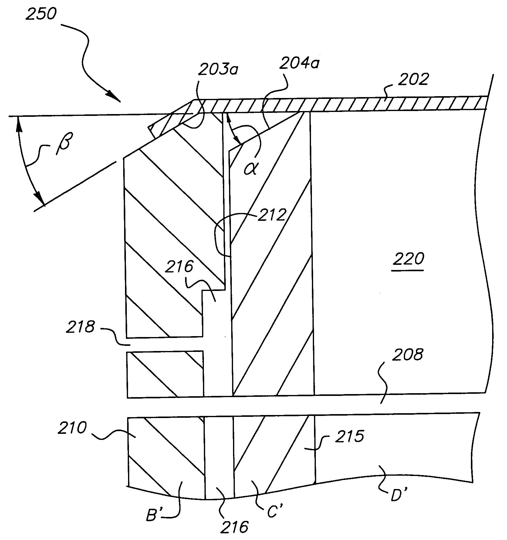
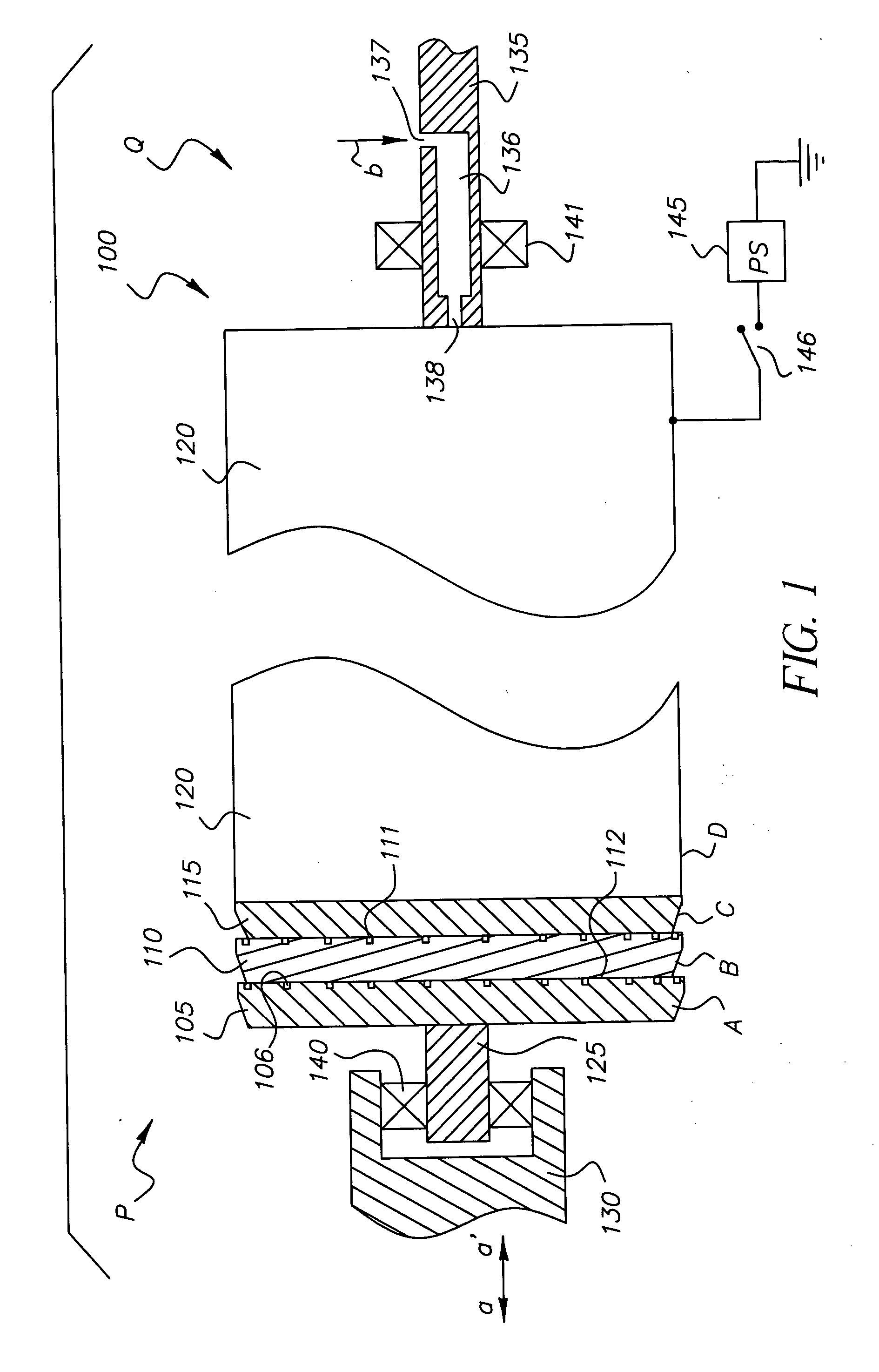
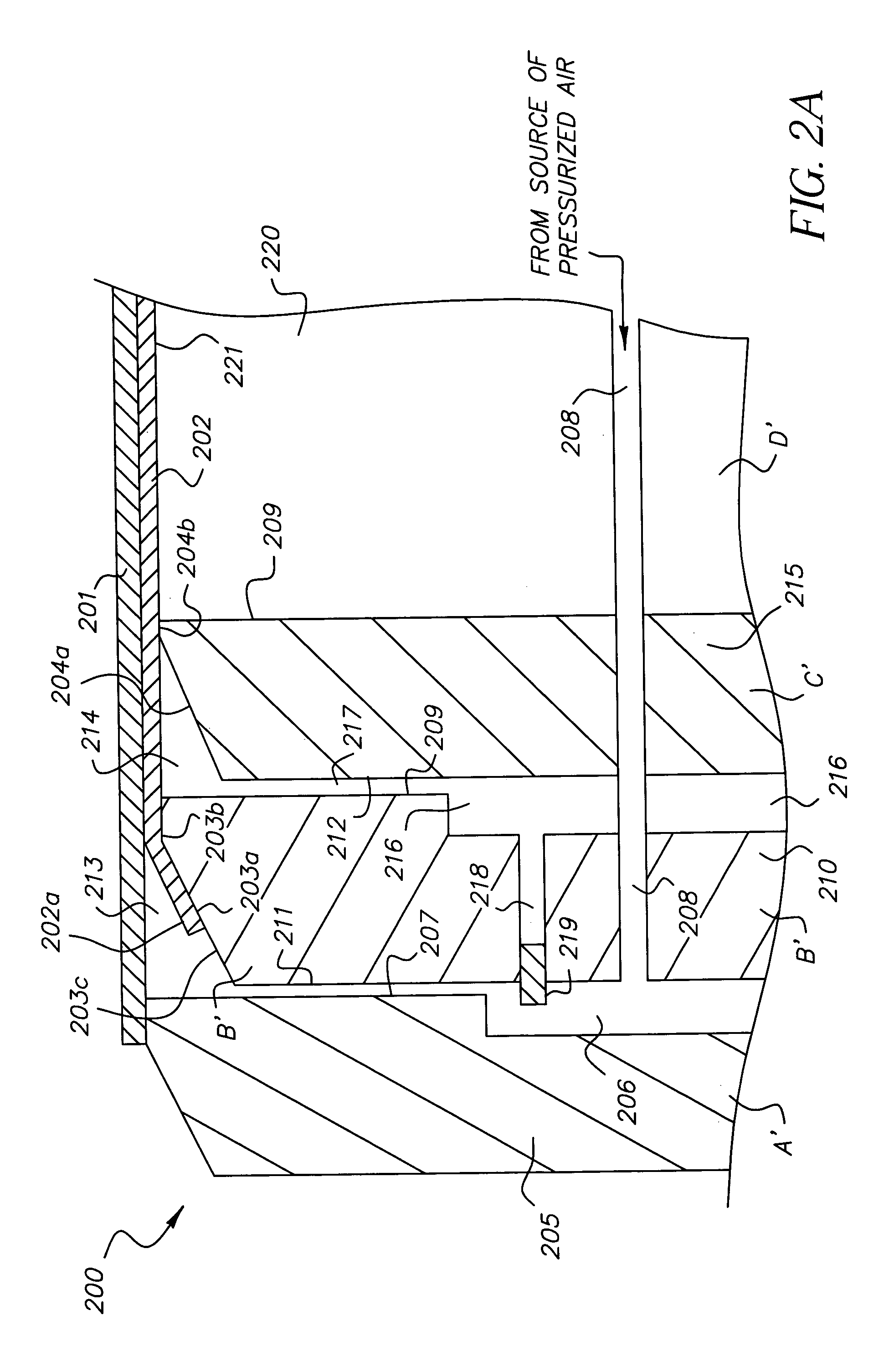
[0036] The subject invention discloses a novel sleeve-replacement fixture (SRF) for aiding replacement of an inner sleeve member (ISM) of a double-sleeved roller (DSR). The invention, used in conjunction with a partly disassembled DSR, is briefly described in the next paragraph and then described in detail with accompanying figures.

[0037] The DSR for use in conjunction with the invention is inclusive of a mandrel, with the ISM gripping the mandrel and an outer sleeve member (OSM) grippingly surrounding the ISM. The DSR has two ends including a disconnectable end supported by a removable support member. The disconnectable end includes a shaft member and a bearing mounted on the shaft member. The mandrel is inclusive of a sleeve-supporting member rotatably supported at the other end of the two ends of the DSR, with the sleeve-supporting member attached to an inner termination plate (ITP) at the disconnectable end. The ITP is also attached to a middle termination plate (MTP) with the ...


PUM


Abstract

A fixture for a double-sleeved roller for assisting replacement of an inner sleeve member (ISM) thereon. The fixture attaches to a fixture-accepting configuration (FAC) including an end plate (EP), which FAC includes passageways for conveying jets of pressurized air to the ISM. The fixture includes a low-surface-energy-coated tubular member (TM) and a mating member (MM) cooperatively forming passageways for creating radially-directed air jets at the perimeter of the MM. The MM and EP cooperatively form another set of passageways for similarly creating air jets. The EP, MM, and TM each includes a cylindrical portion with adjoining tapered portion, the respective tapered portions mutually defined by a conical envelope. The tapered portion of the TM tapers into a cylindrical length merging into a narrowing portion. In all, the air jets are formed from a common source of pressurized air.

Description

CROSS-REFERENCE TO RELATED APPLICATIONS [0001] Reference is made to the following commonly assigned application, the disclosure of which is incorporated herein by reference: [0002] U.S. patent application Ser. No. ______, filed on even filing date herewith, by Steven O. Cormier, et al., entitled, “DOUBLE-SLEEVED ELECTROSTATOGRAPHIC ROLLER”;FIELD OF THE INVENTION [0003] The invention relates to electrostatography and to electrostatographic roller apparatus, and in particular to a fixture and method for use to remove and replace an inner sleeve member of a double-sleeved roller. BACKGROUND OF THE INVENTION [0004] Usage of compliant rollers in electrophotographic apparatus is well known, which compliant rollers may incorporate a removable sleeve member mounted concentrically around a mandrel. Single-sleeved and double-sleeved compliant rollers have been disclosed, e.g., sleeved imaging rollers, sleeved intermediate transfer rollers, and sleeved rollers for use in a fusing station. In a...

Claims


Application Information

Patent Timeline
Patent Type & Authority Applications(United States)
IPC IPC(8): G03G15/00G03G15/01
CPCG03G15/752
Inventor CORMIER, STEVEN O.DUNN, CAROL K.
Owner EASTMAN KODAK CO
Why Eureka
Try Eureka