Wearable electronic device with mode operation indicator

Inactive Publication Date: 2005-06-09
TIMEX GROUP
View PDF11 Cites 19 Cited by
  • Summary
  • Abstract
  • Description
  • Claims
  • Application Information

AI Technical Summary

Benefits of technology

[0008] Another object of the present invention to provide an indicator, using a hand, that conveys to a user of an electronic device that the device is in a selected mode in a very user-friendly and fast manner.
[0009] Yet another object of the present invention to provide a user of an electronic device with immediate visual feedback that the device is in a selected mod

Problems solved by technology

What is important however is that the prior art is deficient in providing a suitable analogous indicator in an analog electronic device in which the timer indicator has a low resolution (e.g. one minute).
Moreover, in electronic devices that further the state of the art, such as those described in U.S.

Method used


Image

  • Wearable electronic device with mode operation indicator
  • Wearable electronic device with mode operation indicator
  • Wearable electronic device with mode operation indicator

Examples


Embodiment Construction

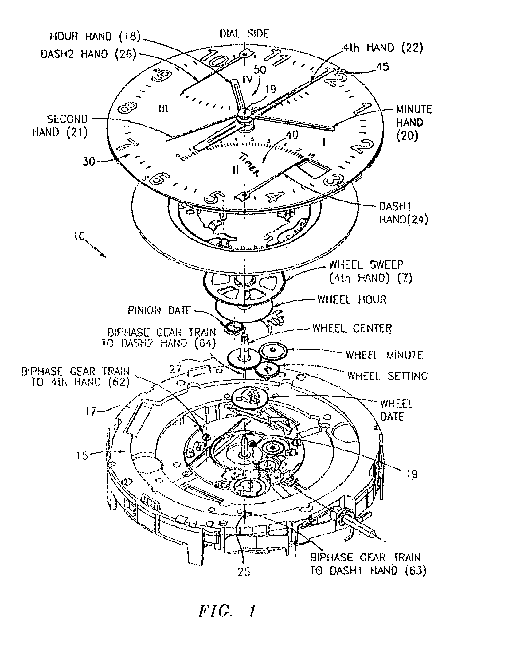
[0026] Reference is first made generally to FIG. 1, which illustrates an exploded view of an electronic device, generally indicated at 10, constructed in accordance with the present invention. Many of the details of FIG. 1 will be omitted for purposes of brevity, but the reader is invited to read U.S. patent application Ser. No. 10 / 441,417 owned by the present assignee, which provides a description of all the details thereof. As this application Ser. No. 10 / 441,417 also provides many other non-essential details related to the present invention, the entire disclosure of this application Ser. No. 10 / 441,417 is incorporated by reference as if fully set forth herein.

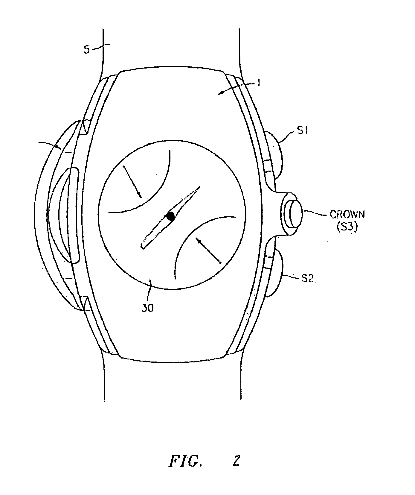
[0027] In a preferred embodiment, and as illustrated in FIG. 2, electronic device 10 is a wearable electronic device, such as but not limited to a wristwatch, generally indicated at 1, which itself will thus comprise other features and parts, namely for example and not limitation, a wrist strap 5 for securing electronic dev...


PUM


Abstract

A method for indicating that a wearable electronic device is operating in a selected mode, wherein the wearable electronic device comprises at least one hand operatively coupled to an actuation mechanism. The method comprises the steps of (a) moving the hand from a first position to a second position, wherein the movement of the hand is through a predetermined sweep angle; (b) moving the hand from the second position back to the first position through the predetermined sweep angle; and (c) repeating at least step (a) and if necessary, repeating step (b); whereby the hand oscillates between the first position and the second position while the wearable electronic device is operating in the selected mode. A wearable electronic device that comprises the foregoing methodology is also provided.

Description

BACKGROUND OF THE INVENTION [0001] This invention relates generally to wearable electronic devices, such as timepieces, and in particular a watch, that comprises unique constructions and methodologies for indicating that the wearable electronic device is operating in a selected mode. Generally speaking, the indication that the electronic device is in the selected mode is carried out by “waggling” or “oscillating” an indicator hand. The present invention is particularly applicable in, and advantageous when incorporated into, an electronic device of the type that displays information, such as time, with the use of hands, such as that found in analog watches (i.e. in an “analog manner”). In this application, the term “oscillate” shall be synonymous with “waggle.”[0002] By way of example and not limitation, the present invention is especially applicable to inform a user (or wearer of the device) when the device is in one or more selected modes, such as a timer mode, and as a particular ...

Claims


Application Information

Patent Timeline
IPC IPC(8): G04B19/04G04B25/00G04C3/14G04C17/00G04F1/00
CPCG04C3/146G04F1/005G04C17/00
Inventor LIZZI, RONALD S.
Owner TIMEX GROUP
Why Eureka
Try Eureka