
Apparatus and method of determining optimal velocity for recording on optical disc

a technology of optical disc and optimal velocity, applied in the direction of digital signal error detection/correction, instruments, recording signal processing, etc., can solve the problems of power adjustment error, recording and/or reproduction error or failure, poor recording quality, etc., to achieve the effect of satisfying the user and maintaining recording quality

Inactive Publication Date: 2005-06-16
SAMSUNG ELECTRONICS CO LTD
View PDF7 Cites 6 Cited by
  • Summary
  • Abstract
  • Description
  • Claims
  • Application Information

AI Technical Summary

Benefits of technology

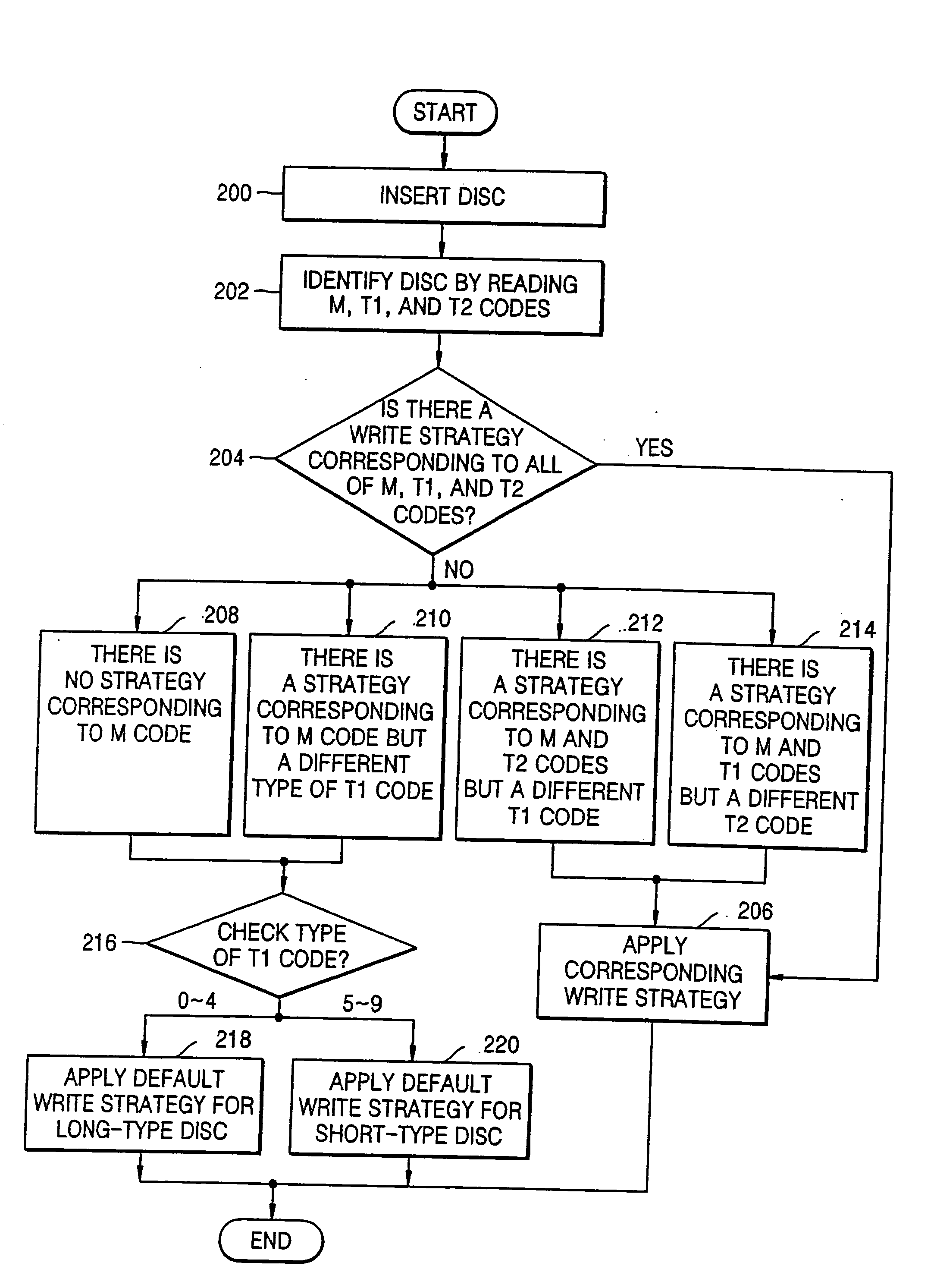
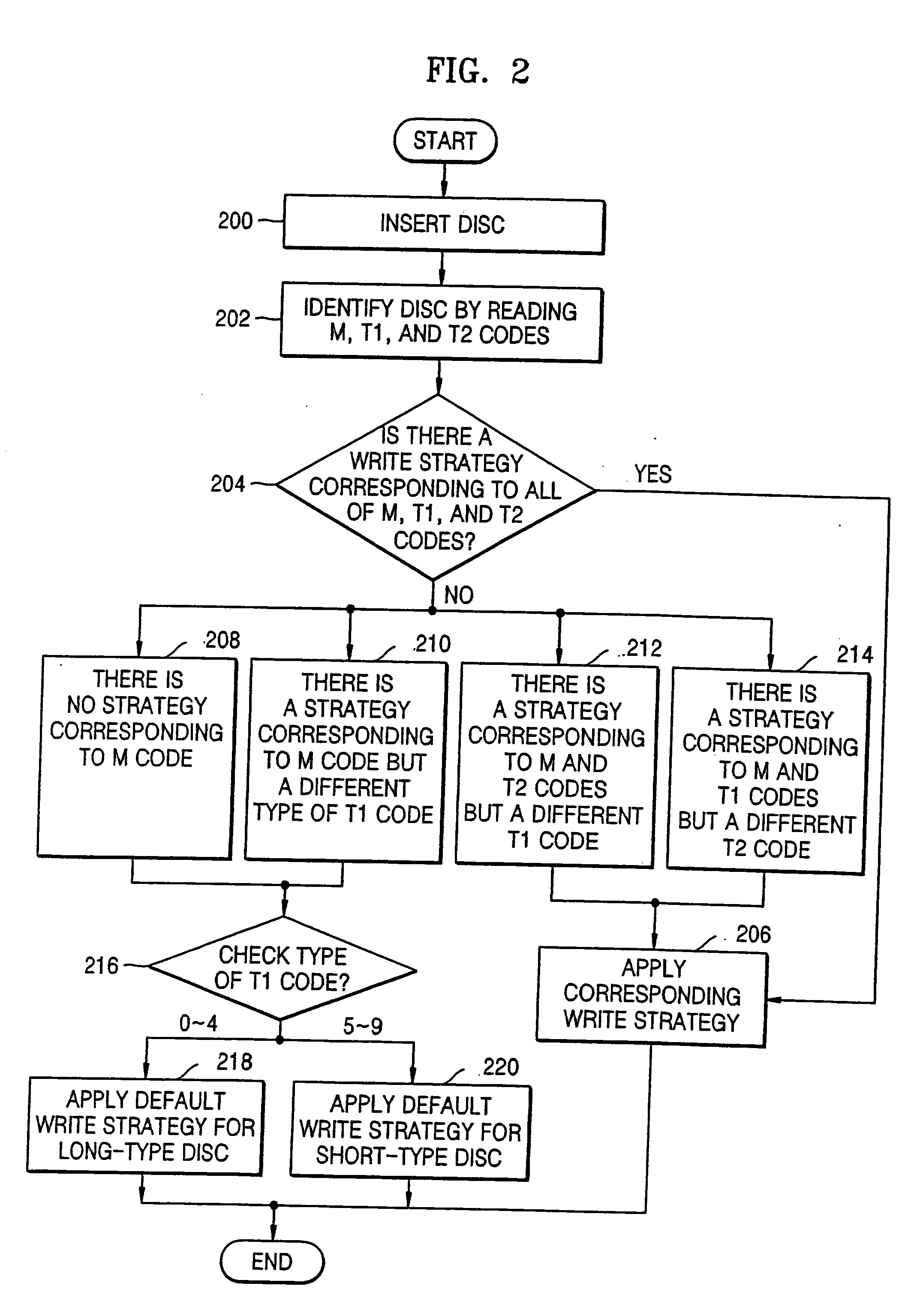
[0010] The invention provides a method of determining an optimum recording velocity for an optical disc, in which an uppermost speed for driving the disc is restricted and power for driving the disc is adjusted according to a recording characteristic of a disc, such that no optimum power control error occurs, thereby maintaining recording quality and satisfying a user.

Problems solved by technology

However, if the disc has different recording characteristic from which the write strategy is designed, the high recording speed may lead to s poor recording quality.
Since different types of discs need to be driven at different velocities, indiscriminately applying a write strategy to a disc may result in a recording and / or reproduction error or failure, a power adjustment error, or poor recording quality, among other problems.

Method used


Image

  • Apparatus and method of determining optimal velocity for recording on optical disc
  • Apparatus and method of determining optimal velocity for recording on optical disc
  • Apparatus and method of determining optimal velocity for recording on optical disc

Examples


Embodiment Construction

[0021] Reference will now be made in detail to the embodiments of the present invention, examples of which are illustrated in the accompanying drawings, wherein like reference numerals refer to the like elements throughout. The embodiments are described below to explain the present invention by referring to the figures.

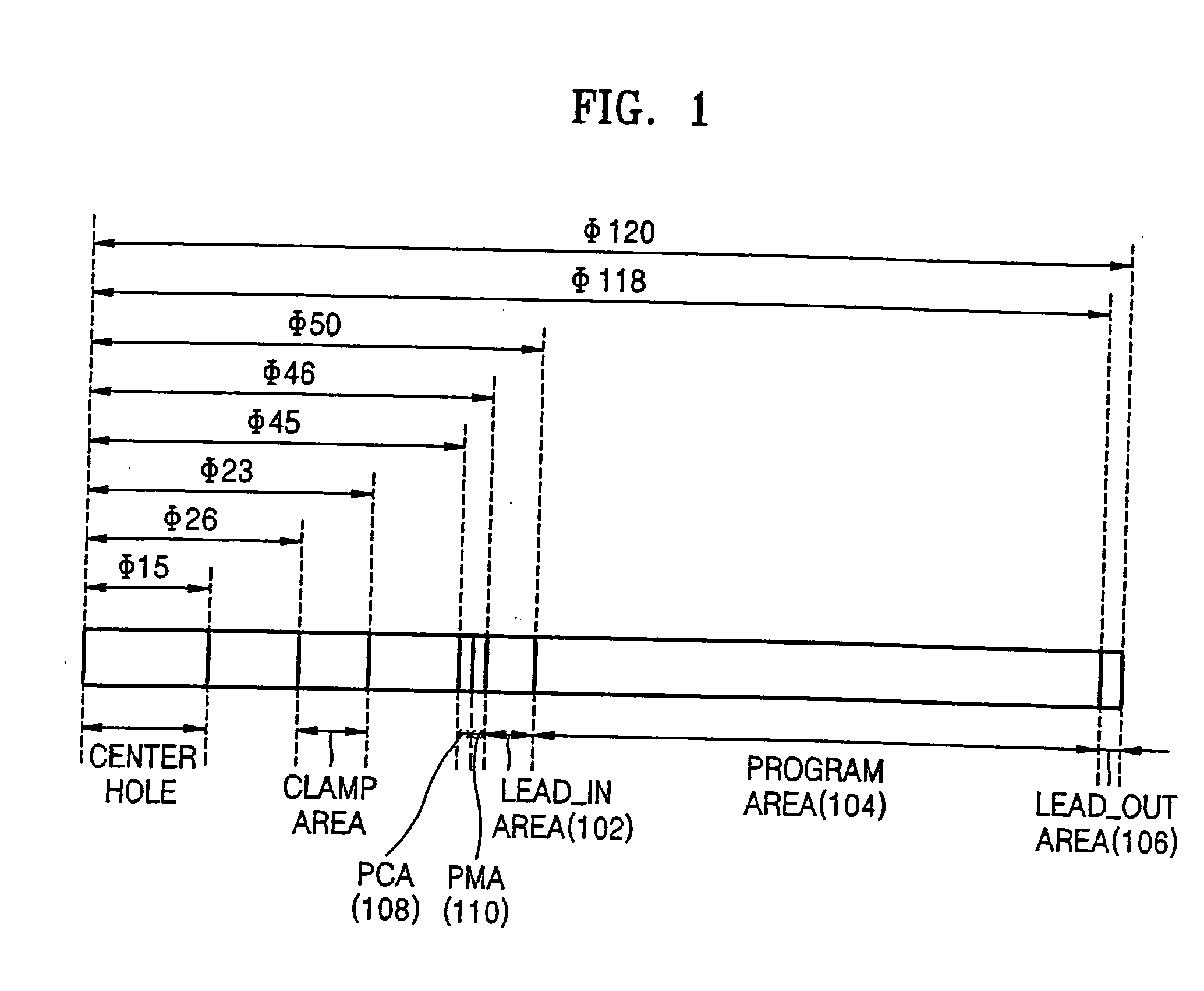
[0022]FIG. 1 is a cross-sectional view showing representative areas of a medium, such as a CD-R disc. The medium includes a lead-in area 102, a program area 104, and a lead-out area 106.

[0023] The lead-in area 102 includes absolute time in pre-groove (ATIP) information regarding medium type, medium size, channel bit length, medium structure, recording power, etc. A power calibration area (“PCA”) 108 is located toward a center area of the medium from the lead-in area 102. In the PCA, operations are performed, such as a test drive for optimum power control (OPC) is performed. A program memory area (“PMA”) 110 is also located toward the center area of the medium. In th...


PUM

PropertyMeasurementUnit
recording speedaaaaaaaaaa
speedaaaaaaaaaa
recording velocityaaaaaaaaaa

Abstract

An apparatus and a method of determining an optimum recording speed for a medium in a disc drive device, the method includes inserting a medium into the disc drive device, determining when disc characteristic information, including a manufacturer code and a type code indicating recording characteristics of the medium, is registered in the disc drive device; and when the disc characteristic information is not registered in the disc drive device, controlling maximum recording speed and target optimum power control power for recording on the medium, according to the type code of the medium.

Description

CROSS-REFERENCE TO RELATED APPLICATIONS [0001] This application claims priority from Korean Patent Application No. 2003-91898 filed on Dec. 16, 2003, in the Korean Intellectual Property Office, the disclosure of which is incorporated herein by reference. BACKGROUND OF THE INVENTION [0002] 1. Field of the Invention [0003] The present invention relates to an apparatus and a method of driving an optical disc, and more particularly, to an apparatus and a method of determining an optimum recording velocity for an optical disc according to whether a recording characteristic of the optical disc has been changed. [0004] 2. Description of the Related Art [0005] Data is recorded on an optical storage medium, e.g. an optical disc, by forming marks on tracks of the optical disc. Optical discs capable of recording, erasing, and reproducing include 650 MB CD-R / RW, 4.7 GB DVD-RAM / R / RW, 4.7 GB DVD+RW, etc., as well as media being developed, such as 23+GB HD-DVD. [0006] A CD-R has pits formed on its...

Claims


Application Information

Patent Timeline
Patent Type & Authority Applications(United States)
IPC IPC(8): G11B5/09G11B7/00G11B7/0045G11B7/006G11B7/007G11B19/26G11B20/10
CPCG11B7/00456G11B19/26G11B7/00736G11B7/0062G11B7/0045
Inventor SHIN, JUNG-MOOKHAN, MYUNG-SU
Owner SAMSUNG ELECTRONICS CO LTD
Learn More