
Apparatus and method for displaying three-dimensional image

a three-dimensional image and apparatus technology, applied in the direction of color television details, instruments, electrical apparatus, etc., can solve the problems of increasing equipment space, difficulty in technique, and inability to smoothly implement stereoscopic images according to the positions of observers, so as to improve user convenience and satisfy users

Inactive Publication Date: 2014-12-09
LG DISPLAY CO LTD
View PDF15 Cites 0 Cited by
  • Summary
  • Abstract
  • Description
  • Claims
  • Application Information

AI Technical Summary

Benefits of technology

The patent describes a technology that synchronizes shutter glasses or a phase retardation plate with a current image to prevent interruption of a 3D image. This happens automatically in real-time, so users don't need to press a synchronization button. It improves user convenience and satisfies users.

Problems solved by technology

The glassless stereoscopic image display scheme is advantageous in that the user does not need to put on glasses but has a problem in that an observation range is fixed to be limited to a small number of users and a stereoscopic image is not smoothly implemented according to positions of observers (or users).
However, because laser reference light must be additionally used to display a 3D image, it has a problem in that there is a difficulty in terms of technique and the space occupied by equipment is increased.
However, the time division stereoscopic image display scheme as described above has the following problem.
Thus, when the display device implementing an image, a system (an electronic device such as a television or the like) in which the display device is installed, and image data are not synchronized, the left eye image may be recognized by the right eye or the right eye image is recognized by the left eye, failing to implement a stereoscopic image.
In this case, however, as time goes by, the display device, the system, and the image data are not synchronized, so the resetting operation must be repeatedly executed, and because the resetting operation itself is performed by the user by directly manipulating the button, making the user feel inconvenient.

Method used


Image

  • Apparatus and method for displaying three-dimensional image
  • Apparatus and method for displaying three-dimensional image
  • Apparatus and method for displaying three-dimensional image

Examples


Embodiment Construction

[0036]Exemplary embodiments of the present invention will now be described with reference to the accompanying drawings.

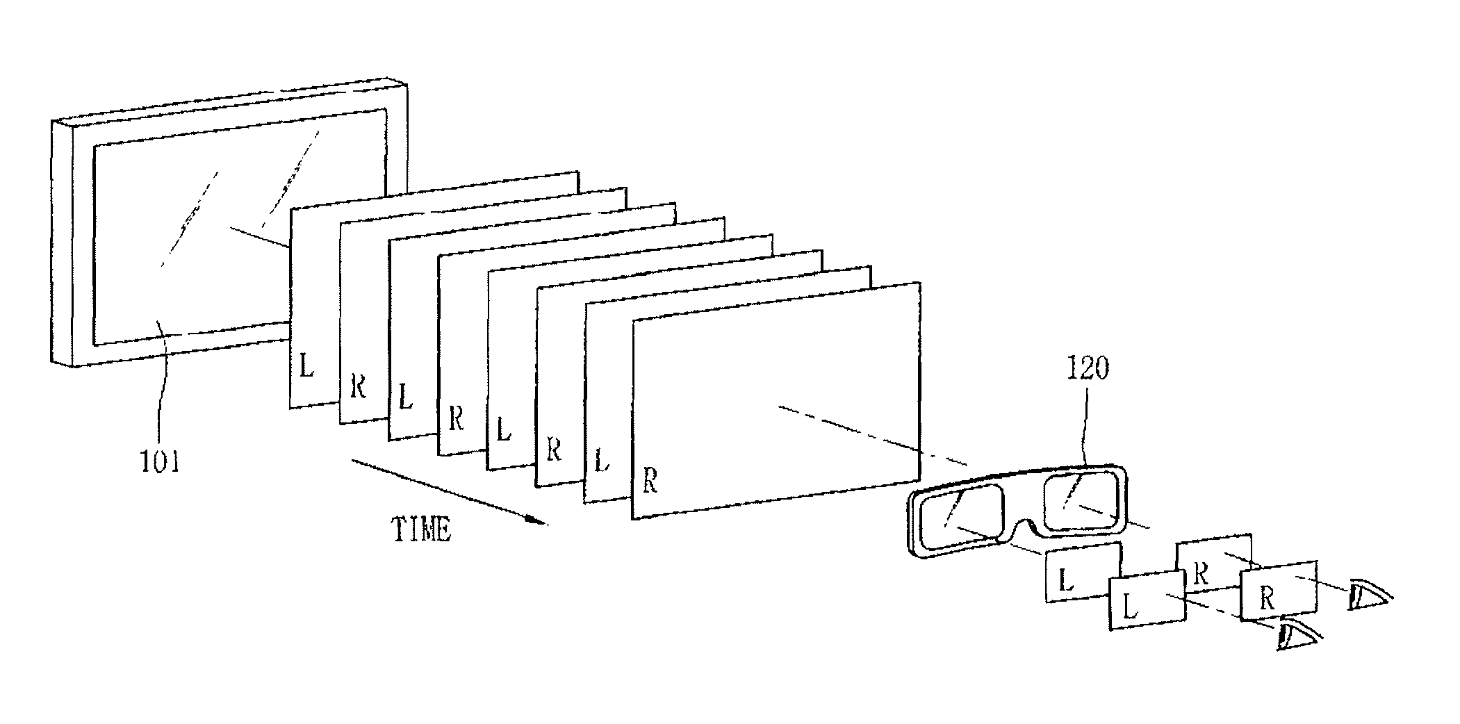
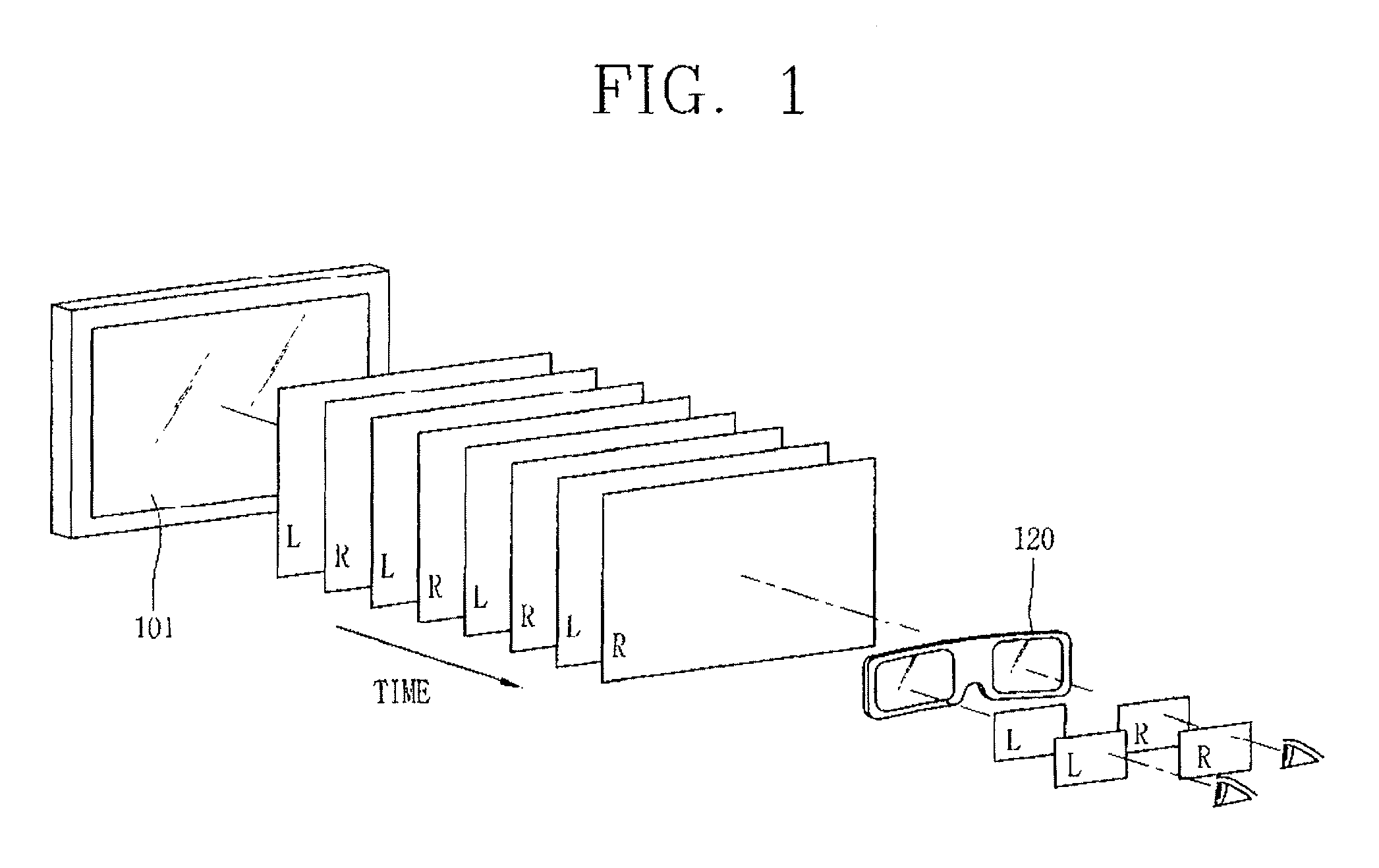
[0037]FIG. 1 is a conceptual view of an apparatus for displaying a three-dimensional (3D) image based on time division according to a first exemplary embodiment of the present invention. In this case, the apparatus for displaying a three-dimensional (3D) image based on time division according to the first exemplary embodiment of the present invention employs shutter glasses.

[0038]As shown in FIG. 1, in the apparatus for displaying a three-dimensional (3D) image based on time division according to the present exemplary embodiment, a left eye image and a right eye image are alternately displayed on a display device 101 such as a liquid crystal display (LCD) or the like. Namely, the left eye image and the right eye image are alternately displayed over time.

[0039]Shutter glasses 120 are synchronized according to the left eye image (L) and the right eye image (R). Namely...


PUM


Abstract

A method for displaying a three-dimensional (3D) image includes: alternately displaying a left eye image and a right eye image; calculating a luminance value of a displayed image to detect a peak value of a luminance value; comparing the detected peak value and a stored peak value, and when the detected peak value corresponds to a right eye peak value, determining that a current image is a right eye image, and when the detected peak value corresponds to a left eye peak value, determining that the current image is a left eye image; outputting a synchronization signal according to the determination result; and making the left eye image and the right eye image reach a user's left eye or right eye according to the synchronization signal.

Description

CROSS-REFERENCE TO RELATED APPLICATIONS[0001]Pursuant to 35 U.S.C. §119(a), this application claims the benefit of earlier filing date and right of priority to Korean Application No. 10-2009-0133779 filed on Dec. 30, 2009, the content of which is incorporated by reference herein in its entirety.BACKGROUND OF THE INVENTION[0002]1. Field of the Invention[0003]The present invention relates to an apparatus and method for displaying three-dimensional (3D) image and, more particularly, to an apparatus and method for displaying a 3D image capable of constantly displaying a 3D image by synchronizing a left-eye image and right-eye image and a display device.[0004]2. Description of the Related Art[0005]Services to be realized for a high speed transmission of information formed based on a high speed information communication network are advancing from a simple ‘listening and speaking service’ such as that of the current communication device to a multimedia service based on a digital terminals ...

Claims


Application Information

Patent Timeline
Patent Type & Authority Patents(United States)
IPC IPC(8): H04N13/04G09G3/00H04N9/47G02B27/22G02B30/25
CPCG09G2360/16H04N13/0434G02B27/2264H04N13/0497H04N13/0438G09G3/003G02B30/24H04N13/337H04N13/341H04N13/398G02B30/25H04N13/00
Inventor YOO, YONG-SUYOO, YONG-TAE
Owner LG DISPLAY CO LTD
Learn More