Sheet metal penetrating tool

Inactive Publication Date: 2005-06-23
HENRIKSEN REID
View PDF19 Cites 2 Cited by
  • Summary
  • Abstract
  • Description
  • Claims
  • Application Information

AI Technical Summary

Benefits of technology

[0006] Although beneficial results may be obtained through use of the sheet metal penetrating tool, as described above, even more beneficial results may be obtained when the handle has a remote anvil end, which is adapted to serve as a striking surface for a hammer. This enables a force to be exerted, by a hammer striking the anvil end, to drive the piercing tip through sheet metal.
[0007] Although benef

Problems solved by technology

Such openings are currently being formed using a screwdriver or a chisel, as there is not a sheet metal penetrating tool suited for this purpose.

Method used


Image

  • Sheet metal penetrating tool
  • Sheet metal penetrating tool
  • Sheet metal penetrating tool

Examples


Embodiment Construction

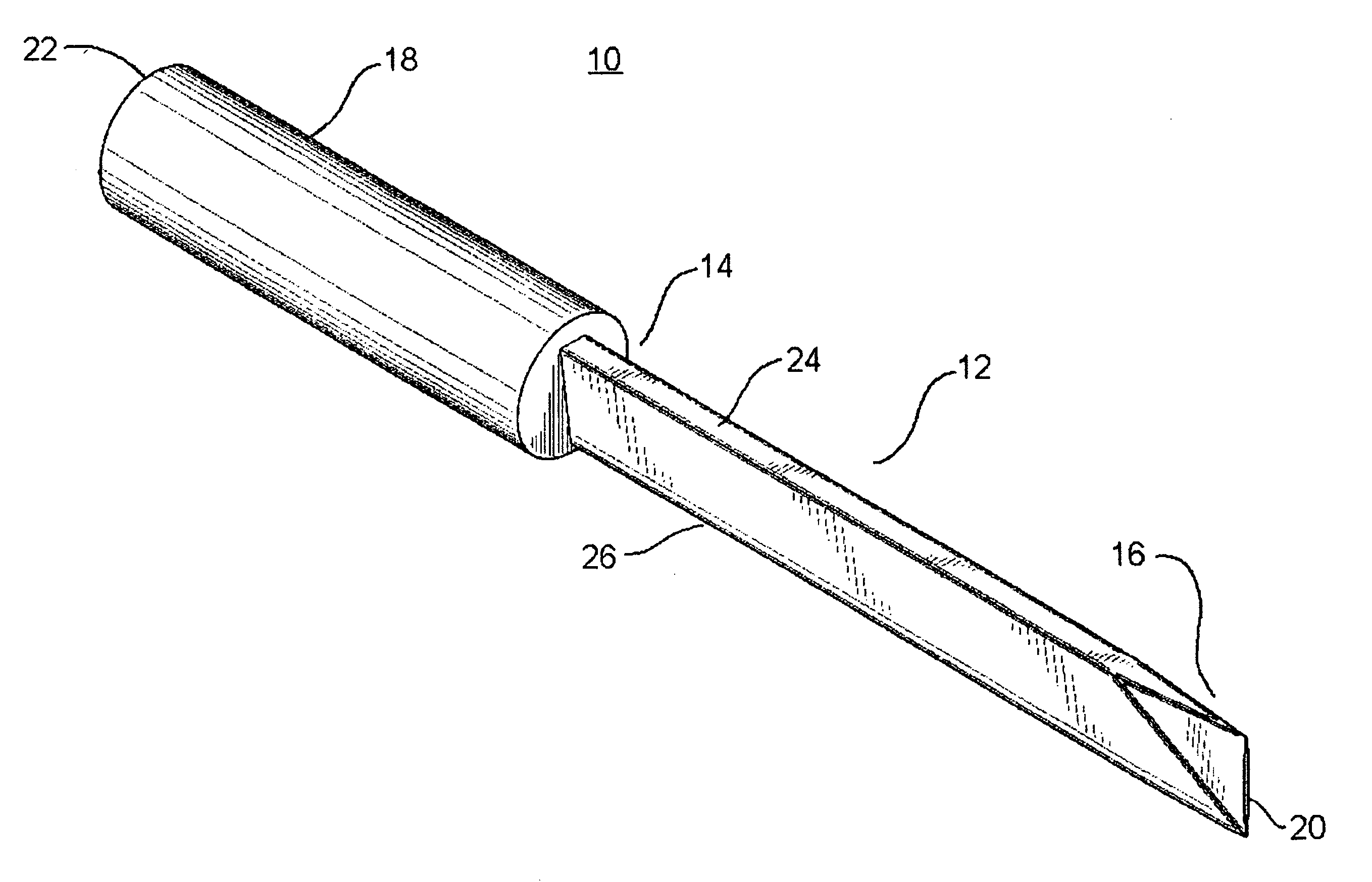
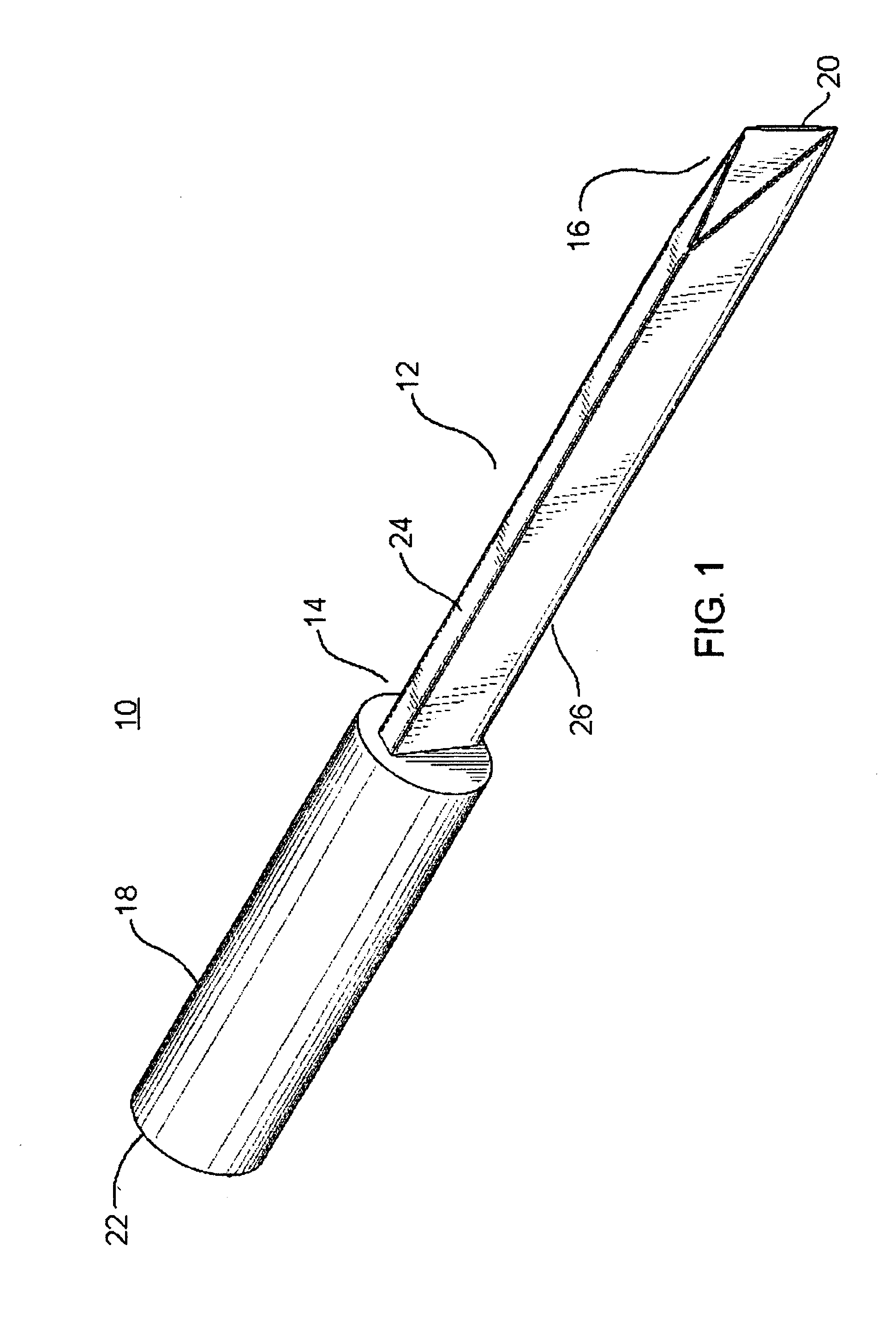
[0017] The preferred embodiment, a sheet metal penetrating tool generally identified by reference numeral 10, will now be described with reference to FIGS. 1 through 8.

[0018] Structure and Relationship of Parts:

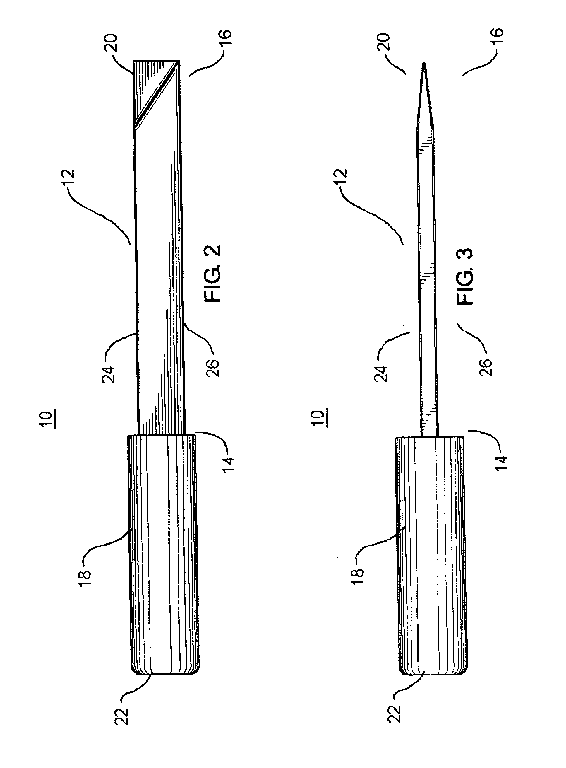
[0019] Referring now to FIG. 1, there is shown a sheet metal penetrating tool 10. The sheet metal penetrating tool has an elongated blade 12 having a first end 14 and a second end 16. Referring to the end elevation view in FIG. 6, the blade is shown to be wedge shaped in cross-section. Referring again to FIG. 1, the sheet metal penetrating tool 10 also comprises a handle 18 at the first end 14 of the blade 12 and a piercing tip 20 at the second end 16 of the blade 12. The handle 18 of the sheet metal penetrating tool 10 has a remote anvil end 22 which is adapted to serve as a striking surface for a hammer, whereby a force is exerted to drive the piercing tip 20 through sheet metal. The piercing tip 20 is shown to comprise the width of the blade 12. It should be understood t...


PUM

PropertyMeasurementUnit
Forceaaaaaaaaaa

Abstract

A sheet metal penetrating tool includes an elongated blade having a first end and a second end. The blade is wedge shaped in cross-section. A handle is positioned at the first end of the blade. A piercing tip is positioned at the second end of the blade.

Description

FIELD OF THE INVENTION [0001] The present invention relates to a penetrating tool developed for use by persons working with sheet metal ducting. BACKGROUND OF THE INVENTION [0002] When plans call for a secondary duct to branch off of a primary duct, sheet metal workers must create an opening in the primary duct large enough to permit the insertion of metal snips. Such openings are currently being formed using a screwdriver or a chisel, as there is not a sheet metal penetrating tool suited for this purpose. SUMMARY OF THE INVENTION [0003] What is required is a sheet metal penetrating tool suited for making openings in existing ducting or light gauge metal. [0004] According to the present invention there is provided a sheet metal penetrating tool, which includes an elongated blade having a first end and a second end. The blade is wedge shaped in cross-section. A handle is positioned at the first end of the blade. A piercing tip is positioned at the second end of the blade. [0005] With...

Claims


Application Information

Patent Timeline
IPC IPC(8): B23D29/02B23D43/02B25D3/00B26F1/32
CPCB26F1/32
Inventor HENRIKSEN, REID
Owner HENRIKSEN REID
Why Eureka
Try Eureka