

Spring Captive Loaded Fastener Retainer
- Summary
- Abstract
- Description
- Claims
- Application Information
AI Technical Summary
Benefits of technology
Problems solved by technology
Method used
Image

Examples
Embodiment Construction
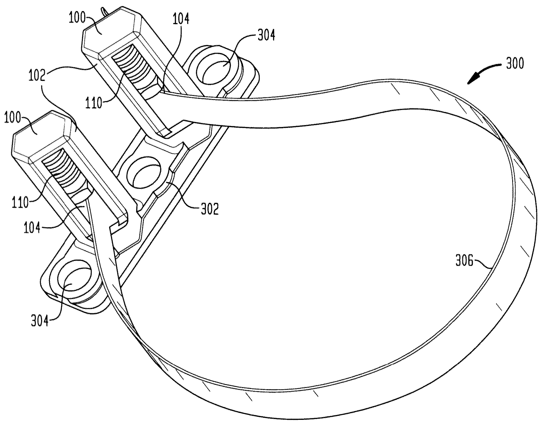
[0016]In at least one embodiment of the present invention, a spring-loaded captive fastener retainer provides a user-friendly system to mechanically fasten units (e.g., panels, cabinets, etc.) to other units. Generally, the retainer is spring-loaded to force a fastener to extend beyond the unit. The retainer also provides guidance to the fastener so that it is secured within the unit and travels in a predictable path. In this way, it is easier for a user to manipulate and / or guide the fastener to contact and / or interlock with another unit or device.
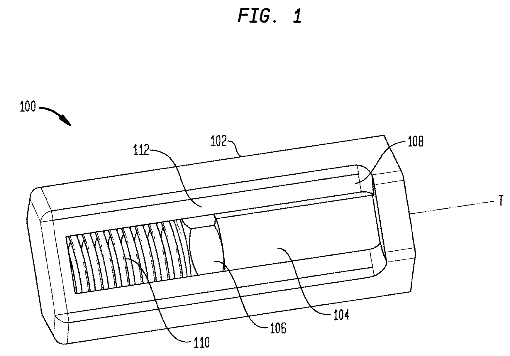
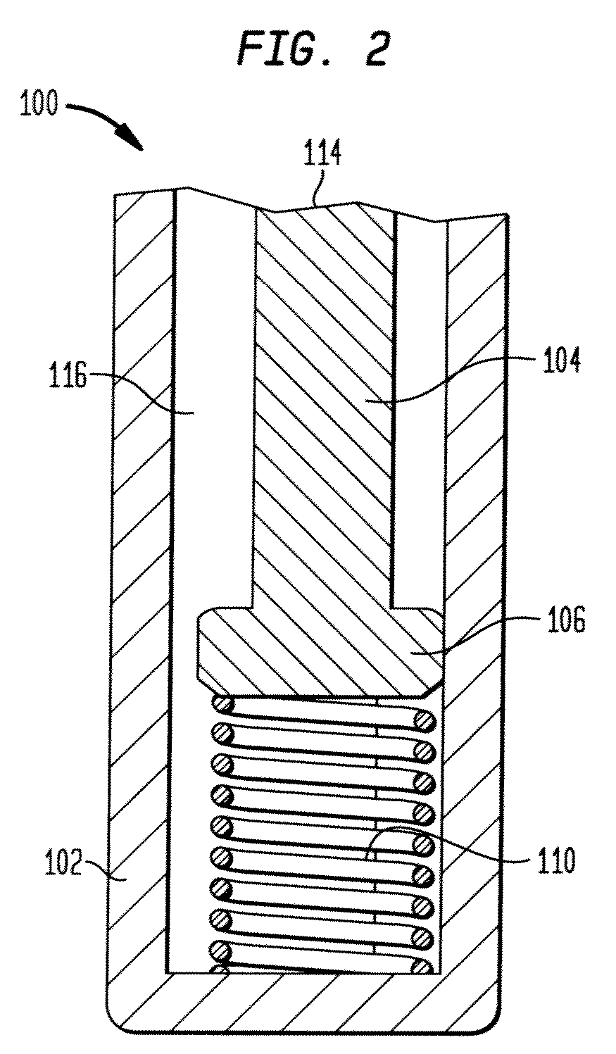
[0017]FIG. 1 depicts a back-top-side perspective view of a retainer 100 according to an embodiment of the present invention. Retainer 100 has a housing 102 that partially or completely encloses a fastener 104, which may have a fastener head 106, such that fastener 104 is generally slidably aligned along a housing channel 108 in a travel direction T (e.g., a travel axis). Retainer 100 also includes an elastic member 110. In some embodiment...
PUM
 Abstract
Description
Claims
Application Information