Optical conveyors

a technology of optical conveyors and optical dividers, applied in the direction of instruments, etc., can solve the problems of insufficient application, limited range, and inability to demonstrate in practice,

Inactive Publication Date: 2013-08-01
NEW YORK UNIV
View PDF2 Cites 1 Cited by
  • Summary
  • Abstract
  • Description
  • Claims
  • Application Information

AI Technical Summary

Benefits of technology

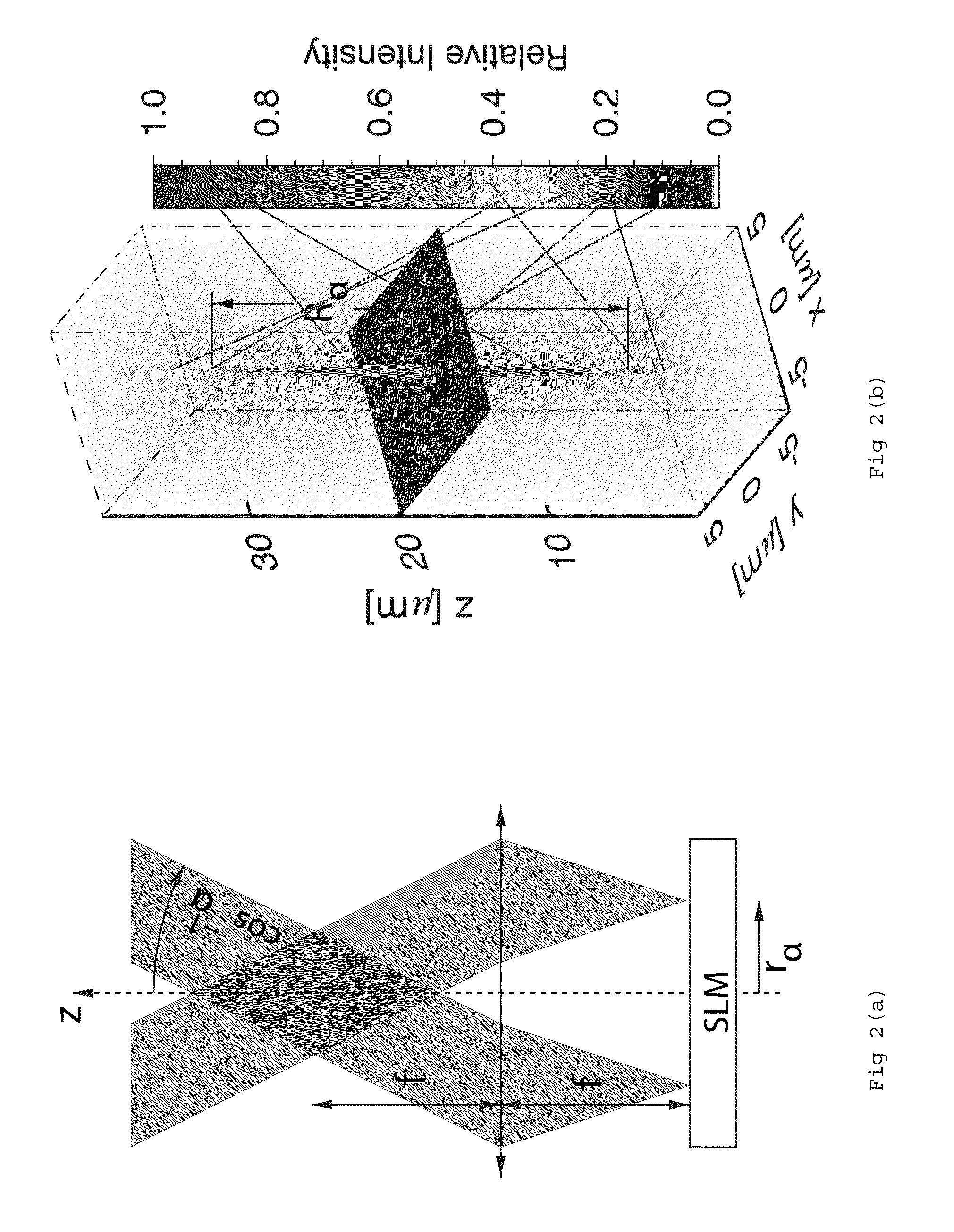
[0006]Another embodiment of the present invention relates to a computer-implemented machine for manipulating an object. The machine includes a processor; and a tangible computer-readable medium operatively connected to the processor and including computer code configured to control the process; generating a first beam of coherent light; generating a second beam of coherent light, the second beam and the first beam being coaxial, having a frequency ω and polarization ê, and propagating along the {circumflex over (z)} direction; and thereby exerting a retrograde optical force for driving on an object.

Problems solved by technology

By this definition an optical tweezer is not a tractor beam because of its inherently limited range.
The latter distinction reflects the need to establish boundary conditions for the standing wave on both sides of the transported object, thereby inherently limiting its range.
This property has been predicted to be possible in both acoustic and optical Bessel beams, but has not yet been demonstrated in practice.
However, both of these two categories of tractor beams present drawbacks that serve as a barrier for practical application.

Method used


Image

  • Optical conveyors
  • Optical conveyors
  • Optical conveyors

Examples


Embodiment Construction

[0014]In the following detailed description, reference Is made to the accompanying drawings, which form a part hereof. In the drawings, similar symbols typically identify similar components, unless context dictates otherwise. The illustrative embodiments described in the detailed description, drawings, and claims are not meant to be limiting. Other embodiments may be utilized, and other changes may be made, without departing from the spirit or scope of the subject matter presented here. It will be readily understood that the aspects of the present disclosure, as generally described herein, and illustrated in the figures, can be arranged. substituted, combined, and designed in a wide variety of different configurations, all of which are explicitly contemplated and made part of this disclosure.

[0015]A category of tractor beams is described herein in addition to the two categories of tractor beams noted above, recoil force and solenoidal waves. The described tractor beams qualitatively...


PUM


Abstract

Optical conveyors providing motive force to objects. The optical conveyors are one-sided and are able to exert forces on illuminated objects that are directed opposite to the direction of the light's propagation.

Description

CROSS REFERENCE TO RELATED APPLICATION[0001]This application claims priority from U.S. Provisional Patent Applications 61 / 593,128 filed Jan. 31, 2012 and is herein incorporated, by reference in its entirety.STATEMENT OF GOVERNMENT INTEREST[0002]The United States Government has certain rights in this invention pursuant to National Institute of Health Contract Nos. DMR-0855741 and DMR-0922680.BACKGROUND OF THE INVENTION[0003]Transportation of materials by a traveling wave has been investigated previously. Generally, the term “tractor beam” refers to a traveling wave that has the capacity to transport material back to its source. By this definition an optical tweezer is not a tractor beam because of its inherently limited range. Nor is an optical conveyor belt a tractor beam, which Is created from, a standing wave rather than a traveling wave. The latter distinction reflects the need to establish boundary conditions for the standing wave on both sides of the transported object, thereby...

Claims


Application Information

Patent Timeline
Patent Type & Authority Applications(United States)
IPC IPC(8): G03H1/04
CPCG03H1/04G03H2001/0077G03H1/2294
Inventor RUFFNER, DAVID B.GRIER, DAVID G.
Owner NEW YORK UNIV
Why Eureka
Try Eureka