Vent plug for self-contained viscous liquid dispenser

Active Publication Date: 2005-06-23
KIMBERLY-CLARK WORLDWIDE INC
View PDF22 Cites 5 Cited by
  • Summary
  • Abstract
  • Description
  • Claims
  • Application Information

AI Technical Summary

Problems solved by technology

Therefore it often takes an undesirably high pressure differential to activate the vent.
The plastic parts can often warp or deform to the point that the sealing ability of the vent becomes deficient.

Method used


Image

  • Vent plug for self-contained viscous liquid dispenser
  • Vent plug for self-contained viscous liquid dispenser
  • Vent plug for self-contained viscous liquid dispenser

Examples


Embodiment Construction

[0027] Reference will now be made in detail to embodiments of the invention, one or more examples of which are illustrated in the drawings. Each example is provided by way of explanation of the invention, not meant as a limitation of the invention. For example, features illustrated or described as part of one embodiment, may be used with another embodiment, to yield still a further embodiment. It is intended that the present invention include modifications and variations to the embodiments described herein.

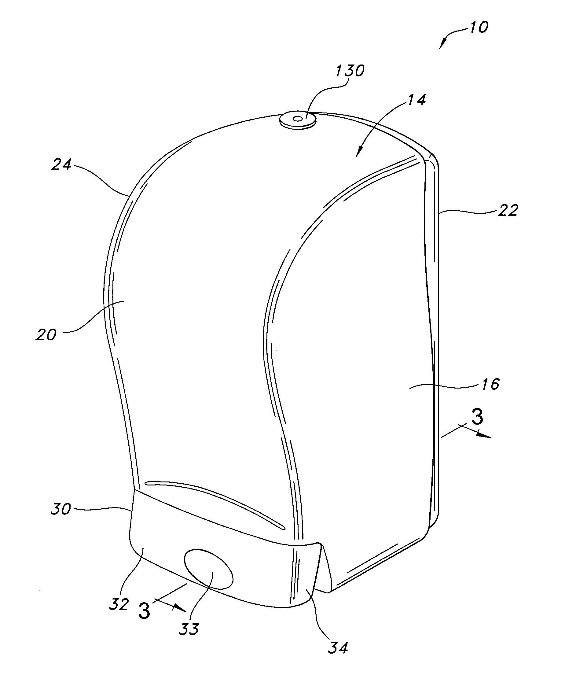
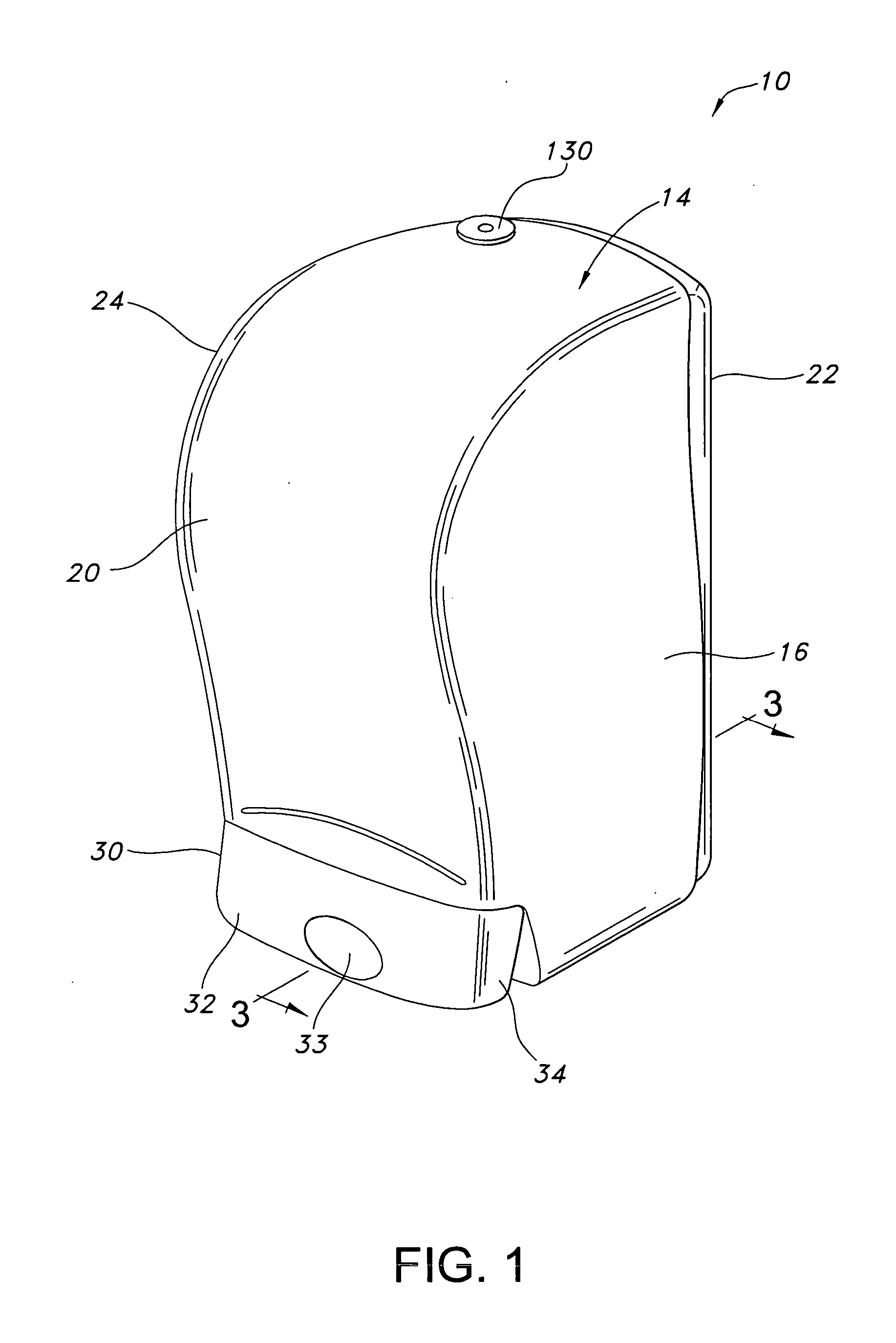
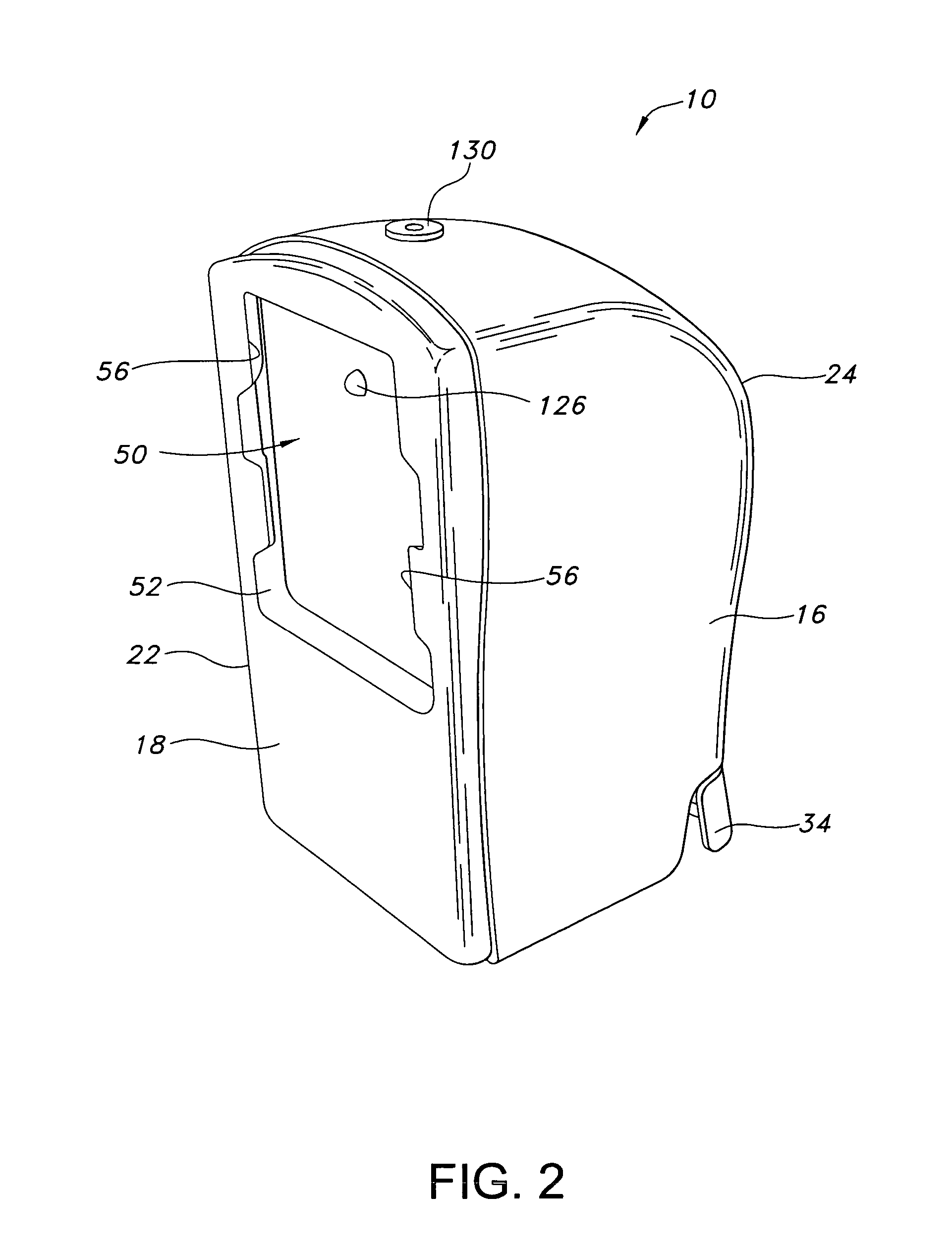
[0028] The present invention relates to a venting mechanism for use with any manner of liquid dispenser. The venting mechanism is particularly well suited for use with any manner of viscous liquid dispenser, for example soap dispensers, lotion dispenser, and the like. Examples of dispensers that may benefit from the vent valve of the present invention are described in WO 02 / 49490 A1 as well as U.S. Pat. No. 6,516,976 to Lewis et al., U.S. Pat. No. 6,533,145 to Lewis et al., U.S. ...


PUM


Abstract

A self-contained viscous liquid dispenser having an improved vent valve is provided. The vent valve includes a plug member having a sealing ridge at its perimeter. The vent valve is activated at reduced pressure differentials between the inside and outside of the dispenser. The vent valve also provides redundant sealing capability.

Description

BACKGROUND OF THE INVENTION [0001] Various configurations and models of liquid dispensers, particularly liquid soap dispensers, are well known in the art. Conventional dispensers typically employed in public restrooms and the like are wall-mounted units that typically include a housing or structure that contains the liquid to be dispensed. The dispensers typically include a delivery device, such as a dosing pump, and a device such as a lever or button for actuating the dosing pump. [0002] Many dispensers have a vent valve. The vent valve serves to allow air to enter the reservoir as the liquid in the reservoir is dispensed. When the differential pressure between the inside and outside of the dispenser reaches a prescribed level, the vent valve opens and allows air to enter and replace the liquid that was dispensed. The opening in the dispenser through which the air flows is desirably small so as to be inconspicuous and help prevent leaks. Therefore it often takes an undesirably high...

Claims


Application Information

Patent Timeline
IPC IPC(8): A47K5/12B67D7/06B05B11/00B65D51/16B67D3/00F16K15/14F16K24/06
CPCA47K5/1204F16K24/06B05B11/0018B05B11/00442A47K5/12A47K5/00B05B11/0039
Inventor LEWIS, RICHARD PAULBACHTEL, RANDALL MARC
Owner KIMBERLY-CLARK WORLDWIDE INC
Why Eureka
Try Eureka