A golf club head having a bridge member and a weight positioning system

a golf club head and weight positioning technology, applied in the field of golf club heads, can solve the problems of golfers unable to adjust the center of gravity, golfers may tend to misdirect the golf shot,

Active Publication Date: 2005-06-23
KARSTEN MFG CORP
View PDF37 Cites 219 Cited by
  • Summary
  • Abstract
  • Description
  • Claims
  • Application Information

AI Technical Summary

Benefits of technology

[0011] In yet a further embodiment of the invention, a golf club head comprises a striking face that provides a contact area for engaging a golf ball and a rear cavity opposite the striking face. The golf club head further includes a bridge member extending across the rear cavity and a weight positioning assembly integral to the bridge member. The weight positioning assembly includes a

Problems solved by technology

Most conventional golf club heads have a fixed center of gravity, which does not allow golfers to make adjustments to the cent

Method used


Image

  • A golf club head having a bridge member and a weight positioning system
  • A golf club head having a bridge member and a weight positioning system
  • A golf club head having a bridge member and a weight positioning system

Examples


Embodiment Construction

[0031] The following discussion and accompanying figures disclose various iron golf clubs in accordance with the present invention. Each golf club includes a golf club head with a weight positioning system for varying a position of a center of gravity of the golf club head.

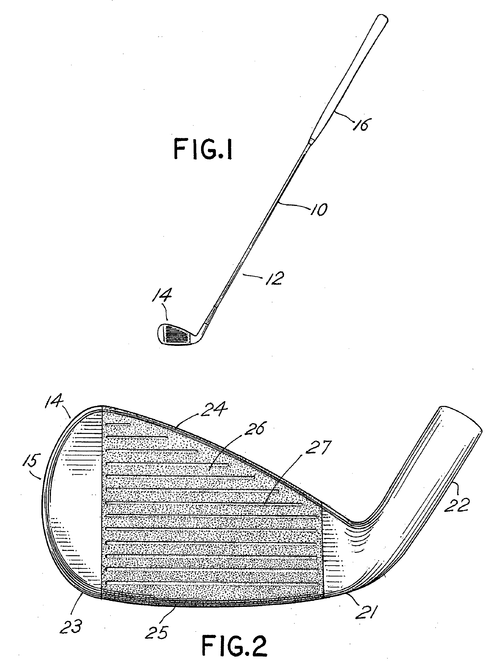
[0032] Referring to FIG. 1, golf club 10 includes a shaft12 and a golf club head 14. The golf club head 14 of FIG. 1 may be representative of an iron golf club head of the present invention. The shaft 12 of golf club 10 may be made of various materials such as steel, titanium, graphite, or a composite material. A grip 16 is positioned on the shaft 12 to provide a golfer with a slip resistant surface on which to grasp golf club 10.

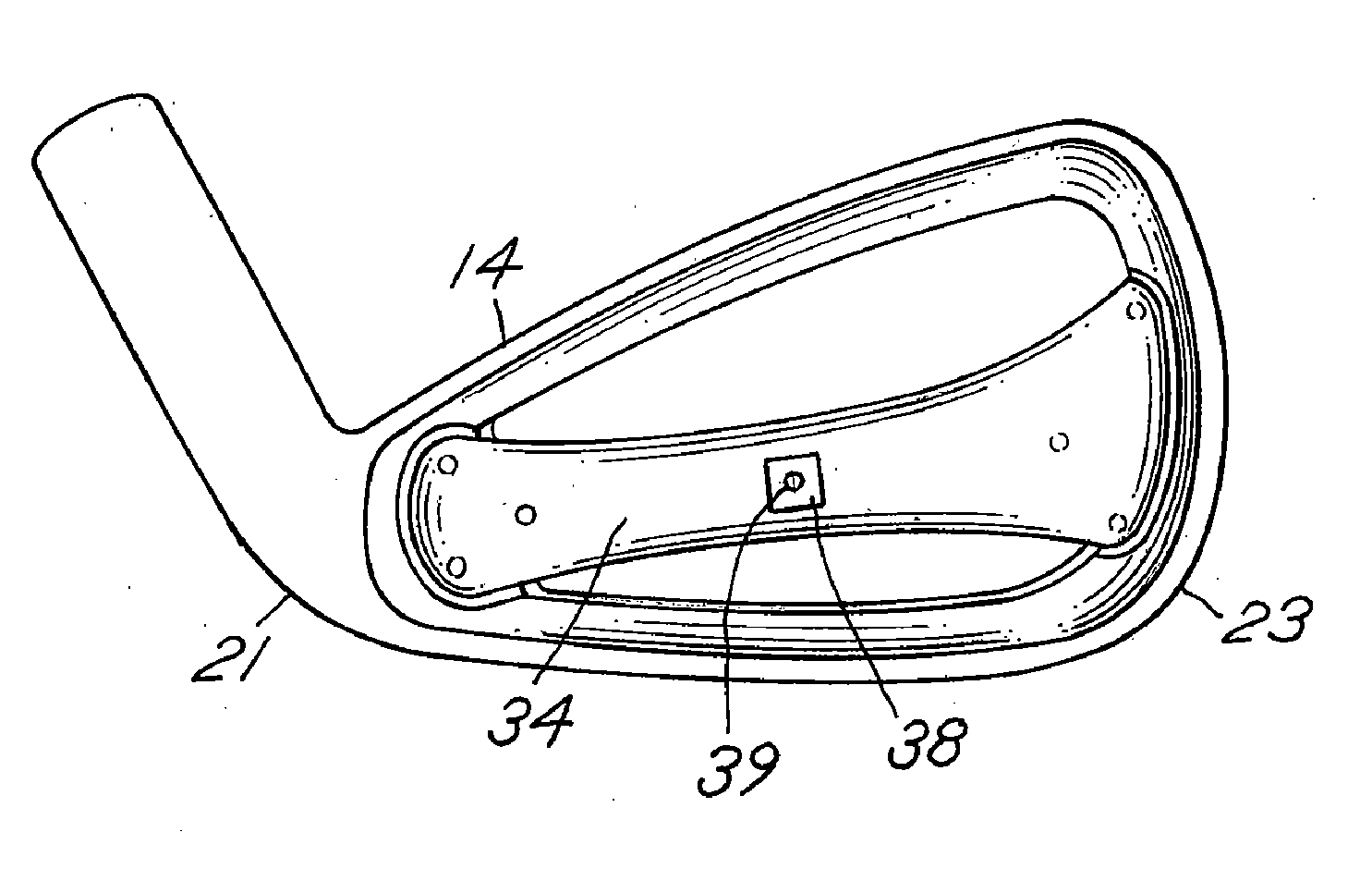
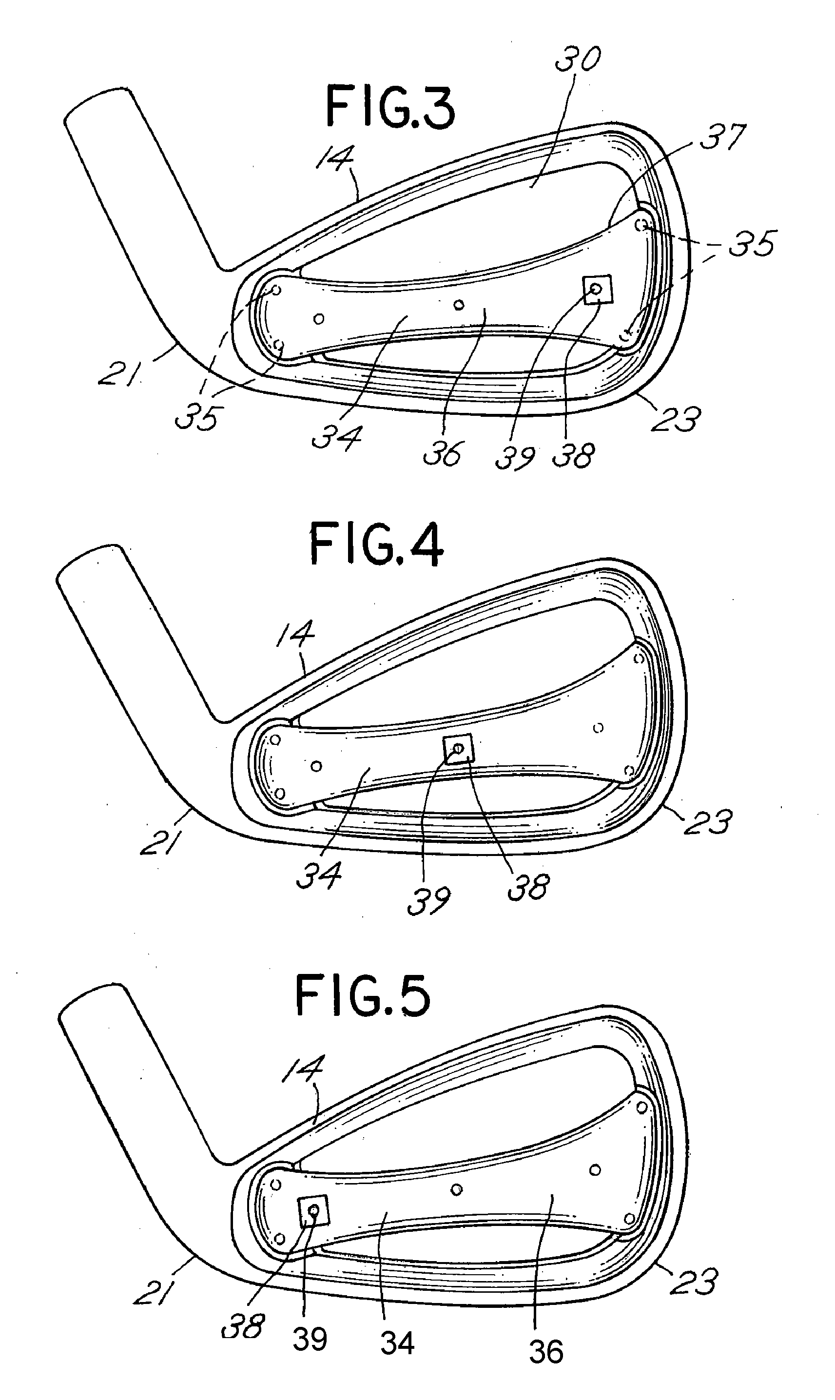
[0033] As shown in FIG. 2, the golf club head 14 comprises a body 15 that includes a heel 21 and toe 23, the body 15 extending between the heel 21 and the toe 23. The heel 21 is attached to a hosel 22 for connecting the shaft 12 of FIG. 1 to the golf club head 14. The body 15 also inclu...


PUM


Abstract

A golf club head is disclosed that includes a weight integral to a bridge member extending across a cavity back golf club head. The weight modifies a position of a center of gravity of the golf club head. The weight is independently movable in multiple directions to further vary the center of gravity of a golf club head.

Description

BACKGROUND OF INVENTION [0001] 1. Field of the Invention [0002] The present invention relates to golf club heads. More particularly, the invention concerns a golf club head having a bridge member and a weight positioning system for modifying a position of a center of gravity of the golf club head. [0003] 2. Description of Background Art [0004] A golf club head generally includes a substantially planar contact area for engaging a golf ball and propelling the golf ball in an intended direction. One factor that determines whether the golf ball is propelled in the intended direction relates to a position of a center of gravity of the golf club head. When the center of gravity is positioned behind the point of engagement on the contact surface, the golf ball follows a generally straight route. When the center of gravity is positioned to a side of the point of engagement, however, the golf ball may follow a route that curves left or right, which is often referred to as a hook or a slice. ...

Claims


Application Information

Patent Timeline
IPC IPC(8): A63B53/04
CPCA63B53/047A63B2053/0433A63B2053/0491A63B2053/045A63B60/02A63B53/0433A63B53/045A63B53/04
Inventor STITES, JOHN THOMASTAVARES, GARY GENE
Owner KARSTEN MFG CORP
Why Eureka
Try Eureka