

Drainage system for use in masonry block construction
- Summary
- Abstract
- Description
- Claims
- Application Information
AI Technical Summary
Benefits of technology
Problems solved by technology
Method used
Image

Examples
Embodiment Construction
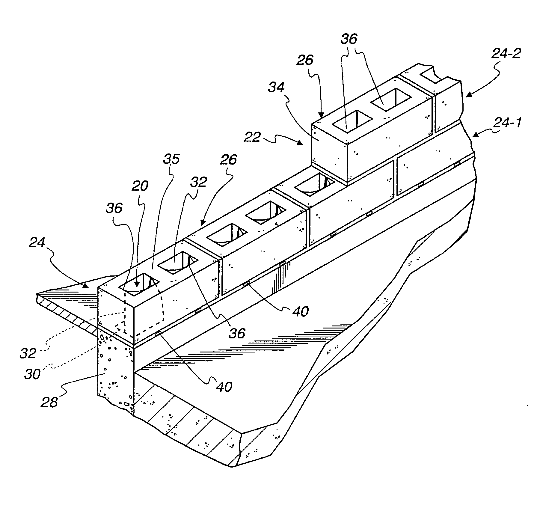
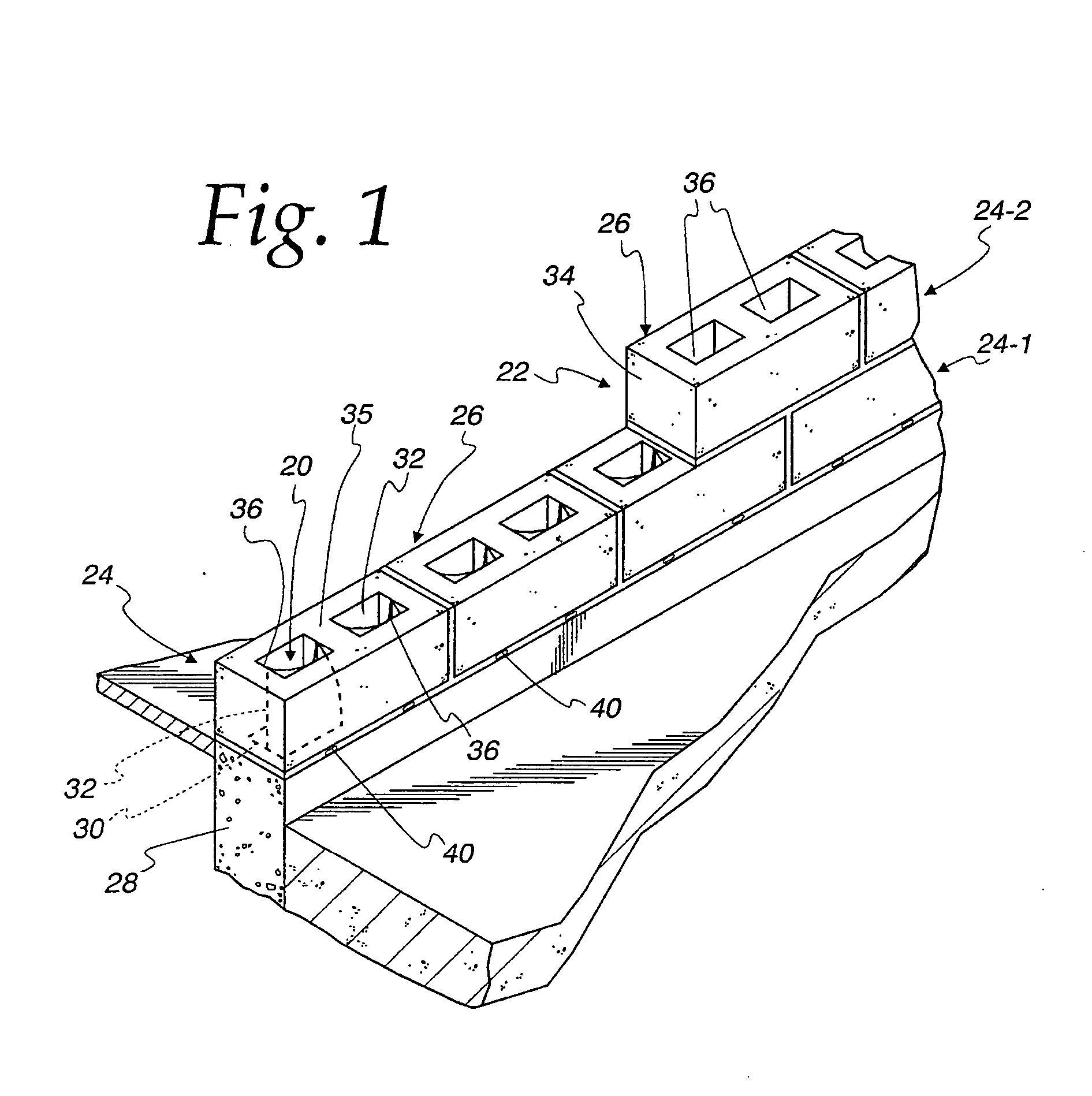
[0046] Referring to FIG. 1, a drainage system 20 is illustrated in connection with concrete masonry unit (CMU) wall construction. In the illustrated embodiment of the invention, the drainage system 20 is used in a single wythe masonry wall construction 22 formed by courses 24 of CMUs 26. The wall construction 22 is used on a building structure including a foundation wall 28. In the illustrated embodiment of the invention, the foundation wall 28 comprises a concrete wall. The foundation wall could be of block construction, as will be apparent to those skilled in the art.
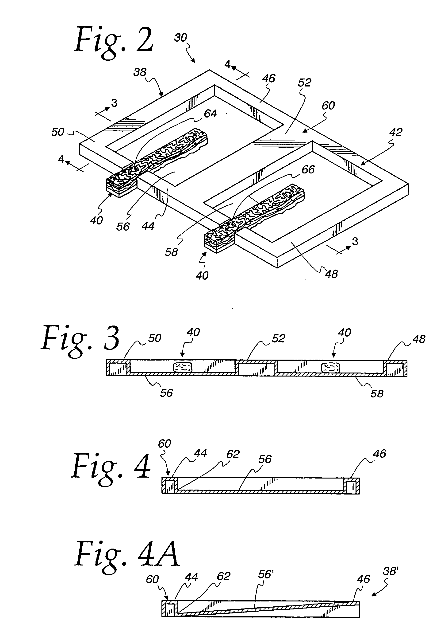
[0047] Referring also to FIG. 10, the drainage system 20 comprises a tray 30 and a pair of blocks 32 of water permeable material.
[0048] CMUs 26 most typically have a nominal height of eight inches, a nominal length of sixteen inches and come in nominal widths of eight, ten or twelve inches. Actual sizes are about {fraction (3 / 8)} inches less to allow for a ⅜-inch mortar joint. The CMU 26 comprises a hollow concrete ...
PUM
 Abstract
Description
Claims
Application Information