Twist-on wire connector applicator and interlocking wire connectors for use therewith

a technology of interlocking wire connectors and applicators, which is applied in the direction of wrenches, connection end caps, manufacturing tools, etc., can solve the problems of fatigue or repetitive stress injuries, process slow and inefficient, and relatively slow process

Active Publication Date: 2005-06-30
IDEAL IND INC
View PDF35 Cites 2 Cited by
  • Summary
  • Abstract
  • Description
  • Claims
  • Application Information

AI Technical Summary

Benefits of technology

[0008] The present invention is an applicator which automatically feeds and installs twist-on wire connectors. The applicator is lightweight, compact, and portable. In one embodiment, the housing of the device is preferably gun-shaped with an elongated barrel portion, a handle portion and a central case between the barrel and the handle. Within the elongated barrel is a rotatable tube with an opening at one end for receiving a plurality of wire connectors. These connectors are preferably disengagably interlocked wing-type twist-on wire connectors. A spring is disposed in the tube and is compressed when a clip of interlocked wire connectors is fed into the tube. The spring urges the connectors toward the opening of the tube.
[0009] A retaining cap attached to or integral with the barrel is positioned adjacent the opening of the tube and prevents the clip of connectors from prematurely exiting before the connector has been applied to the stripped ends of the wires. Bearings surround a portion of the tube to mount it for rotation within the barrel.

Problems solved by technology

However, applying large numbers of these connectors by hand can lead to fatigue or repetitive stress injuries.
Furthermore, the several steps involved in terminating or connecting wires makes the process slow and inefficient where numerous connections need to be made.
While these twist assist devices address the problem of repetitive motion injury, the many steps still required to apply connectors keep the process relatively slow and in need of improvement in production situations where large numbers of connectors have to be applied.
While this type of apparatus addresses repetitive stress problems and helps to speed up the process of applying connectors by automatically feeding a new connector to the applicator, these devices are bulky and not easily transportable.
In addition, these devices cannot assist tradespeople who quickly move from one location to another.

Method used


Image

  • Twist-on wire connector applicator and interlocking wire connectors for use therewith
  • Twist-on wire connector applicator and interlocking wire connectors for use therewith
  • Twist-on wire connector applicator and interlocking wire connectors for use therewith

Examples


Embodiment Construction

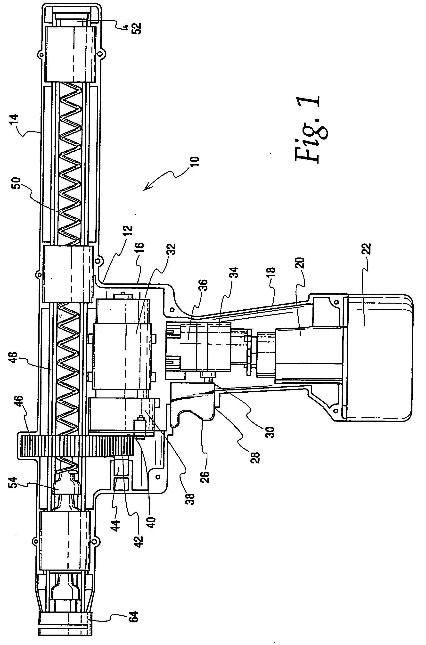
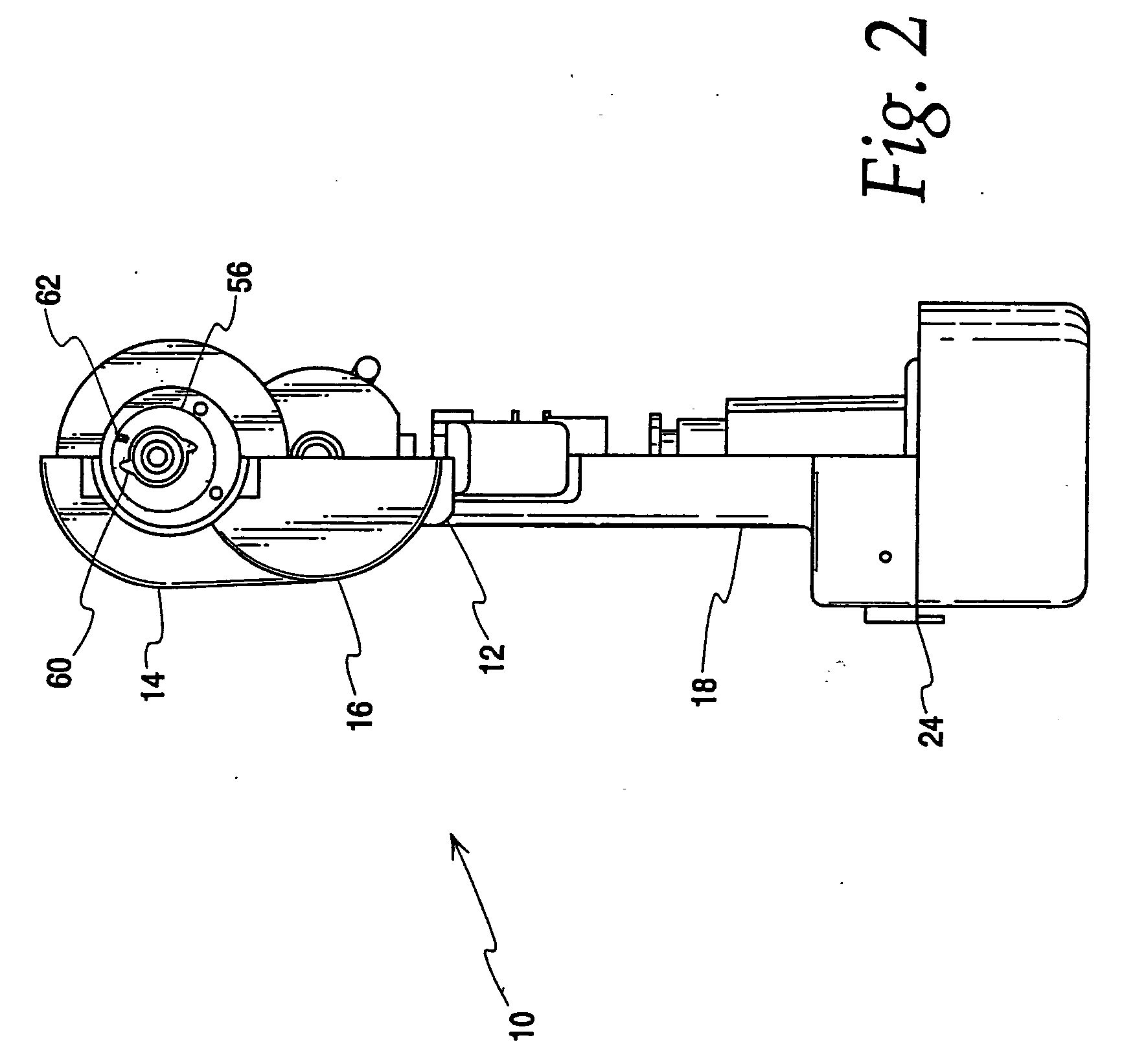
[0021] A wire connector applicator 10 according to the present invention is shown in FIGS. 1-3. Its housing 12 has an appearance generally resembling a standard power drill / driver. The applicator 10 has an elongated barrel 14 which is preferably made of a hard, durable plastic. Extending at about a right angle and slightly off center of the barrel 14 is a handle 18. A central case 16 is disposed between the handle and the barrel. At the lower most end of the handle 18 is an opening to accept a portion 20 of a standard rechargeable battery pack 22. The battery pack is retained by clips 24 (FIG. 2). A trigger 26 extends through an opening 28 in the handle and is biased to extend out from the handle. The trigger is positioned to be accessible by a user's index finger such that the trigger can be squeezed towards the housing to activate a switch 30 for controlling power to an electric motor 32. The electrical circuit between the electric motor, switch and the battery is provided through...


PUM

PropertyMeasurementUnit
cylindrical shapeaaaaaaaaaa
poweraaaaaaaaaa
speedaaaaaaaaaa

Abstract

A wire connector applicator is capable of holding a clip of interconnected twist-on wire connectors in a tube which can be rotated by an electric motor. The connectors rotate with the tube for installation on the ends of stripped electrical wires. The invention is also directed to an interlocking twist-on wire connector which prevents axial separation and relative rotation of similarly configured group or clip of interlocked connectors.

Description

CROSS-REFERENCE TO RELATED APPLICATION [0001] This application claims the benefit of U.S. Provisional Application No. 60 / 517,168, filed on Nov. 4, 2003, which is hereby incorporated by reference.BACKGROUND OF THE INVENTION [0002] This invention is directed to an apparatus for installing twist-on wire connectors onto the ends of stripped electrical wires. The invention also concerns a twist-on wire connector whose shape has been optimized for use with the applicator of the present invention. [0003] Twist-on or screw-on wire connectors have been used for many years to provide a simple and efficient means of mechanically and electrically joining stripped ends of two or more electrical wires. Such connectors typically have a frusto-conical housing or shell with a metallic spring disposed in the interior of the shell. The process of installing one of these twist-on wire connectors usually includes the step of first stripping the insulation off the ends of a number of wires. Next, the twi...

Claims


Application Information

Patent Timeline
Patent Type & Authority Applications(United States)
IPC IPC(8): B25B13/48B25B23/06H01R4/22H01R43/033H02G3/06
CPCB25B13/48B25B23/065H01R4/22Y10T29/53257Y10T29/53209Y10T29/53213H01R43/033
Inventor KESWANI, SUSHILBETHURUM, GARY
Owner IDEAL IND INC
Why Eureka
Try Eureka