Gain stabilizing self-energized brake mechanism

a self-energized, self-energized technology, applied in the direction of mechanical equipment, braking systems, transportation and packaging, etc., can solve the problems of multiplication of braking force, and achieve the effect of increasing braking force, uniform, controllable and predictable increases in braking for

Inactive Publication Date: 2005-06-30
ARVINMERITOR TECH
View PDF22 Cites 14 Cited by
  • Summary
  • Abstract
  • Description
  • Claims
  • Application Information

AI Technical Summary

Benefits of technology

[0007] A brake assembly designed according to this invention includes a first arm pivotally attached to a first pivot and a second arm pivotally attached to a second pivot. Each of the first and second arms includes friction material forming a contact surface for engagement with a rotatable brake member. The first and second pivots are movably mounted to an adjustable member. The first pivot of the first arm is disposed on an opposite side of the contact surface with the rotatable brake member. The second pivot of the second arm is also disposed on an opposite side of the contact surface of the rotatable brake member. The distance between the first and second pivots and the contact surface along with applied pressure on the first and second arms causes rotation of the first and second arms into the rotatable brake member to multiply braking force exerted on the rotatable member. An actuator or other passive means such as a compliant member adjusts the distance between the first and second pivots to control the gain or increase in braking force caused by self-energization. Control of the gain in braking force prevents instability caused by uncontrolled increases in braking forces.
[0008] Another brake assembly according to this invention includes first and second brake pads attached at a first segment by a hinged connection. A second segment of the first and second brake pads are selectively engaged with the rotatable brake member by a threaded rod rotated by an actuator. Contact between the first and second brake pads and the rotating brake member causes the first end to rotate away from the rotating brake member. The hinged connection constrains this rotation resulting in a multiplication in braking force caused by the first and second brake pads being pulled into the rotating brake member. The actuator rotates the threaded rod in a reverse direction to disengage the first and second brake pads from the rotating member. Control of the pressure applied to each brake pad controls the magnitude of self-energization, which results in a stable increase in braking force.
[0010] Another brake assembly of this invention includes a pivot link attachment between the brake pads. One of the brake pads is fixed to the caliper housing such that engagement of one brake pad pulls the other brake pad into engagement with the rotating brake member. A lever or actuator rotates one of the brake pads into engagement with the rotating member. Rotation of one brake pad is translated by way of the pivot link into rotation of the second brake pad. Rotation of the brake pads into the rotating member results in the brake pads being pulled into the rotating member and increased braking force.
[0011] Accordingly, the present invention provides a stable, self-energizing brake assembly with uniform, controllable and predictable increases in braking force.

Problems solved by technology

The hinged connection constrains this rotation resulting in a multiplication in braking force caused by the first and second brake pads being pulled into the rotating brake member.

Method used


Image

  • Gain stabilizing self-energized brake mechanism
  • Gain stabilizing self-energized brake mechanism
  • Gain stabilizing self-energized brake mechanism

Examples


Embodiment Construction

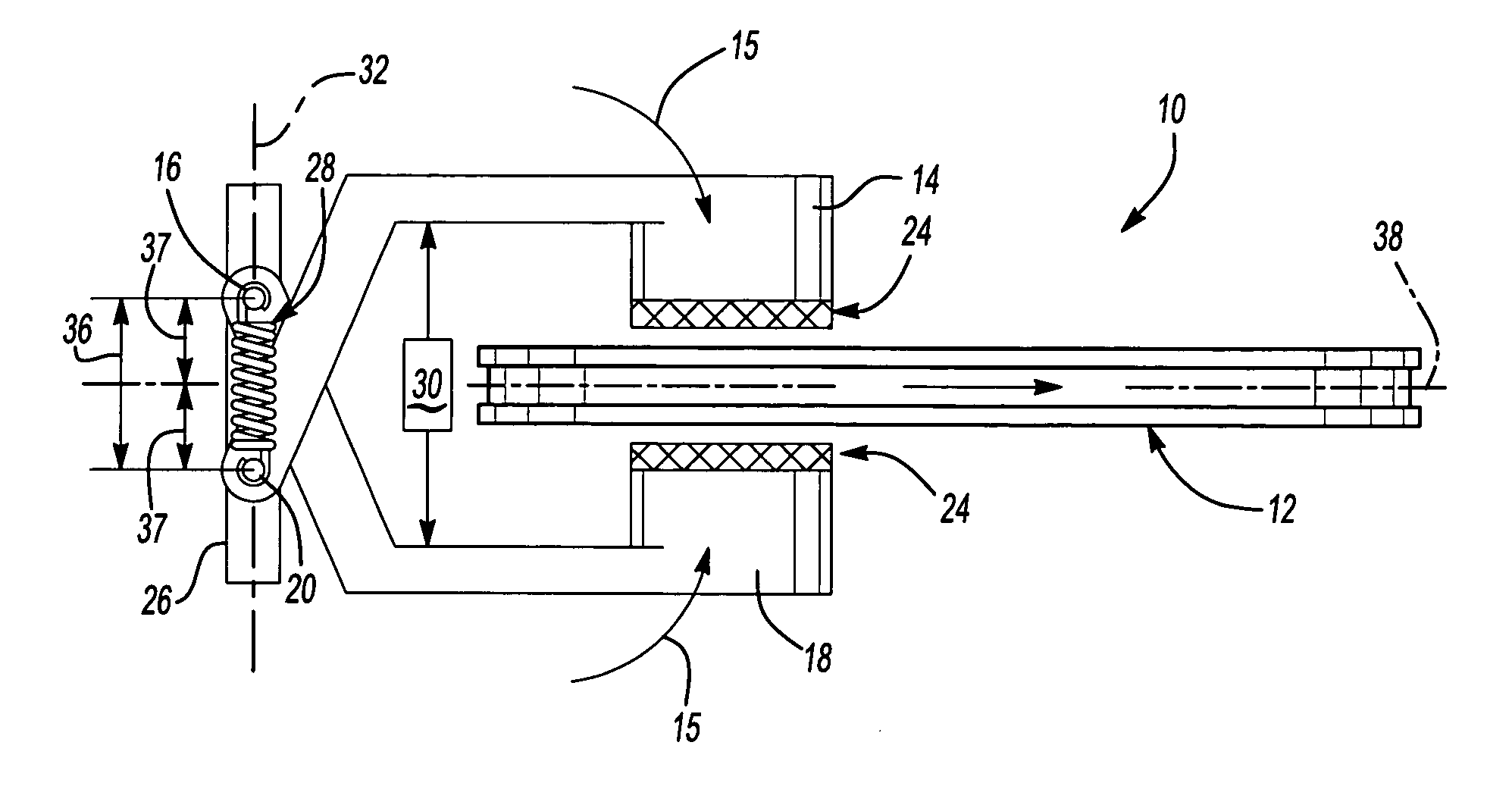
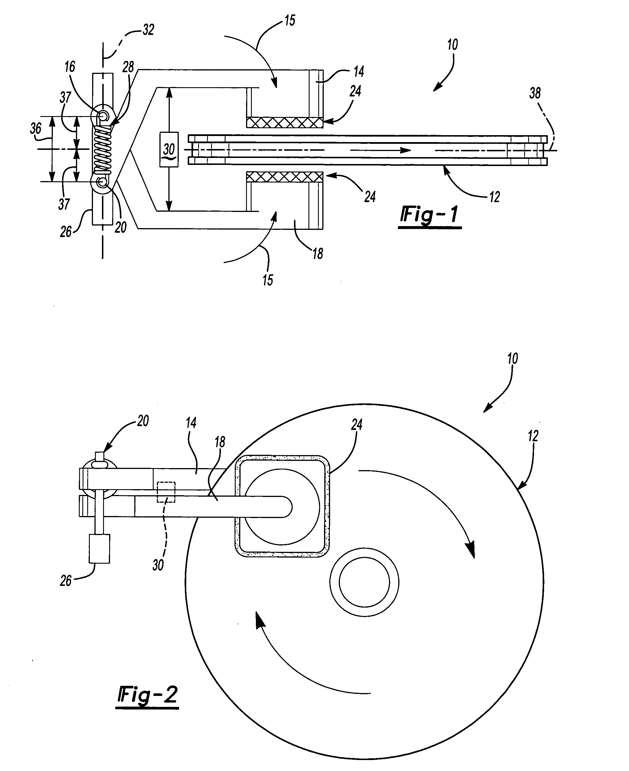
[0026] Referring to FIGS. 1 and 2, a self-energizing brake assembly 10 includes first and second calipers 14, 18 pivotally attached to a support 26. The calipers 14, 18 engage a rotor 12. The contact surface between the calipers 14, 18 and the rotor 12 is formed by friction material 24. Frictional contact between the calipers 14, 18 causes a rotation toward the rotor 12 in a direction indicated by arrows 15 that magnifies braking force applied to the rotor 12.

[0027] A first pivot 20 supports the first caliper 14 and a second pivot 16 supports the second caliper 18. A distance 36 between each of the pivots 16, 20 is adjustable. An actuator 30 is used to adjust the distance 36 between the pivots 16, 20. Friction between the calipers 14, 18 and the rotor 12 pulls the calipers 14,18 in the direction of rotation of the rotor 12. The offset position of the pivots 16, 20 causes each caliper 14,18 to be pulled in the direction of rotation of the rotor 12. The pivots 16, 20 are located on a...


PUM


Abstract

A self-energized disk brake assembly includes gain stabilization features for controlling the multiplication of applied force against a rotatable brake member. The brake assembly includes a first brake pad supported about a first pivot and a second brake pad supported about a second pivot. An actuator applies a force to drive the brake pads into the rotatable brake member. Frictional force between the brake pads and the rotatable brake member pulls the brake pads into further engagement generating an increase in braking force from self-energization. A position of the first and second pivots is adjustable to control the amount of braking force generated from self-energization.

Description

BACKGROUND OF THE INVENTION [0001] This invention generally relates to a disk brake assembly and specifically to a self-energized disk brake assembly including features for stabilizing braking force gain. [0002] Conventional disk brake assemblies require a considerable amount of mechanical force to obtain the required braking force. The mechanical force is typically provided by a hydraulic piston actuated to force brake pads against a rotor. The piston is typically movable within a caliper housing. The caliper housing is either of a fixed or floating configuration. A fixed caliper housing remains fixed relative to the rotor as the brake pads move into contact with the rotor. A fixed caliper includes two pistons for moving the brake pads into engagement with the rotor. A floating caliper uses a single piston that moves one of the brake pads into contact with the rotor, and floats to pull the second pad into contact on an opposite side of the rotor. [0003] A Self-energizing brake crea...

Claims


Application Information

Patent Timeline
Patent Type & Authority Applications(United States)
IPC IPC(8): F16D53/00F16D55/224F16D55/228F16D65/14
CPCF16D53/00F16D2127/08F16D55/228F16D55/2245
Inventor JELLEY, FREDERICK A.KAY, JOSEPH A.BRICHTA, JAMES R.O'REILLY, DENNIS G.KEENEY, CHRISTOPHER S.KWAK, JAEHOKRAMER, DENNIS A.
Owner ARVINMERITOR TECH
Why Eureka
Try Eureka