Generation of image quality adjustment information & image quality adjustment with image quality adjustment information

a technology of image quality adjustment and information, applied in the field of image quality adjustment information and image quality adjustment information, can solve the problem of shortening the total processing time, and achieve the effect of good image quality balance and easy and prompt image quality adjustmen

Inactive Publication Date: 2005-06-30
SEIKO EPSON CORP
View PDF3 Cites 64 Cited by
  • Summary
  • Abstract
  • Description
  • Claims
  • Application Information

AI Technical Summary

Benefits of technology

[0008] The object of the invention is thus to eliminate the drawbacks of the prior art and to execute image quality adjustment of objective image data, in order to attain good image quality balance between ornamental image data and the objective image data. The object of the invention is also to execute easy and prompt image quality adjustment of objective image data by taking into account the image quality of ornamental image data.

Problems solved by technology

Omission of these steps under such conditions desirably shortens the total processing time.

Method used


Image

  • Generation of image quality adjustment information & image quality adjustment with image quality adjustment information
  • Generation of image quality adjustment information & image quality adjustment with image quality adjustment information
  • Generation of image quality adjustment information & image quality adjustment with image quality adjustment information

Examples


first embodiment

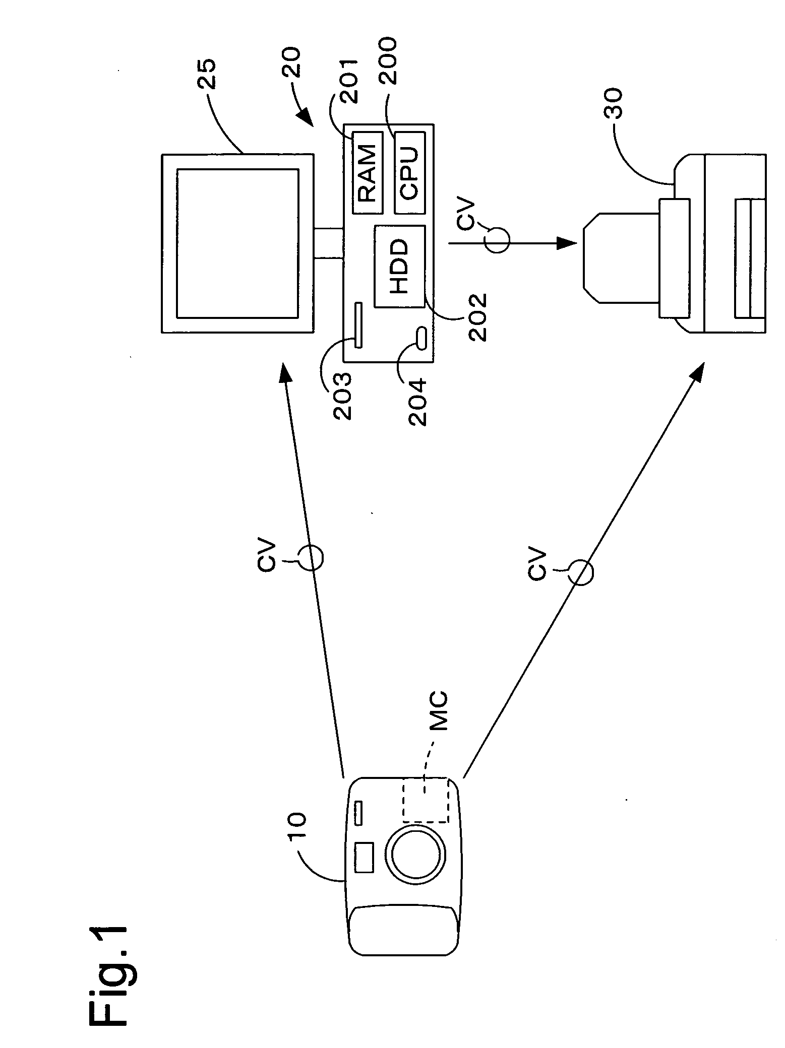
[0054] An image processing system including an image quality adjustment information generation device of a first embodiment is described below with reference to FIG. 1. FIG. 1 schematically illustrates the configuration of the image processing system including the image quality adjustment information generation device of the first embodiment.

[0055] The image processing system includes a digital still camera 10 functioning as an input device to generate image data, a personal computer 20 functioning as the image quality adjustment information generation device to write image quality adjustment information, which is used for image quality adjustment of image data GD, into ornamental image data FD, and a color printer 30 functioning as an output device to output an image corresponding to output image data. The digital still camera 10 may have the image quality adjustment information generation functions of the personal computer 20. The output device is not restricted to the color prin...

second embodiment

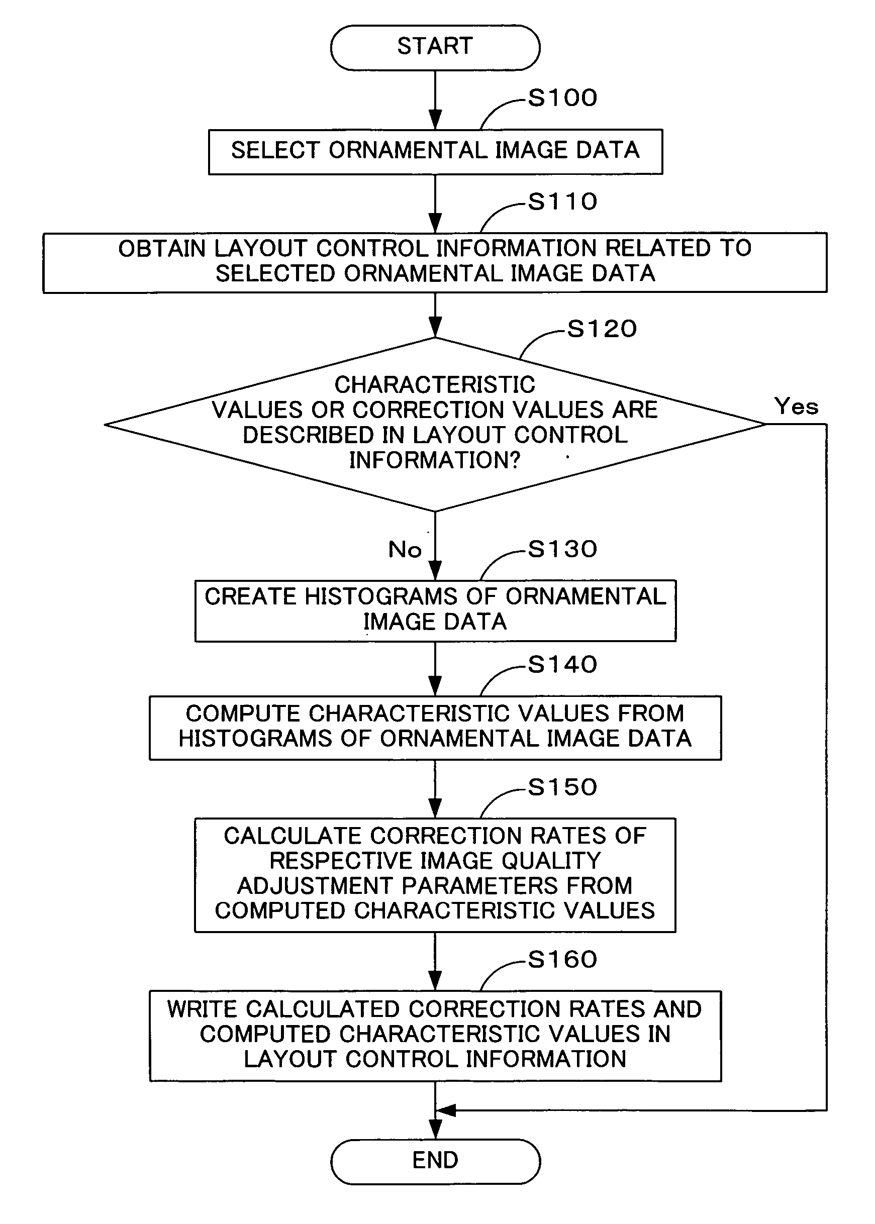
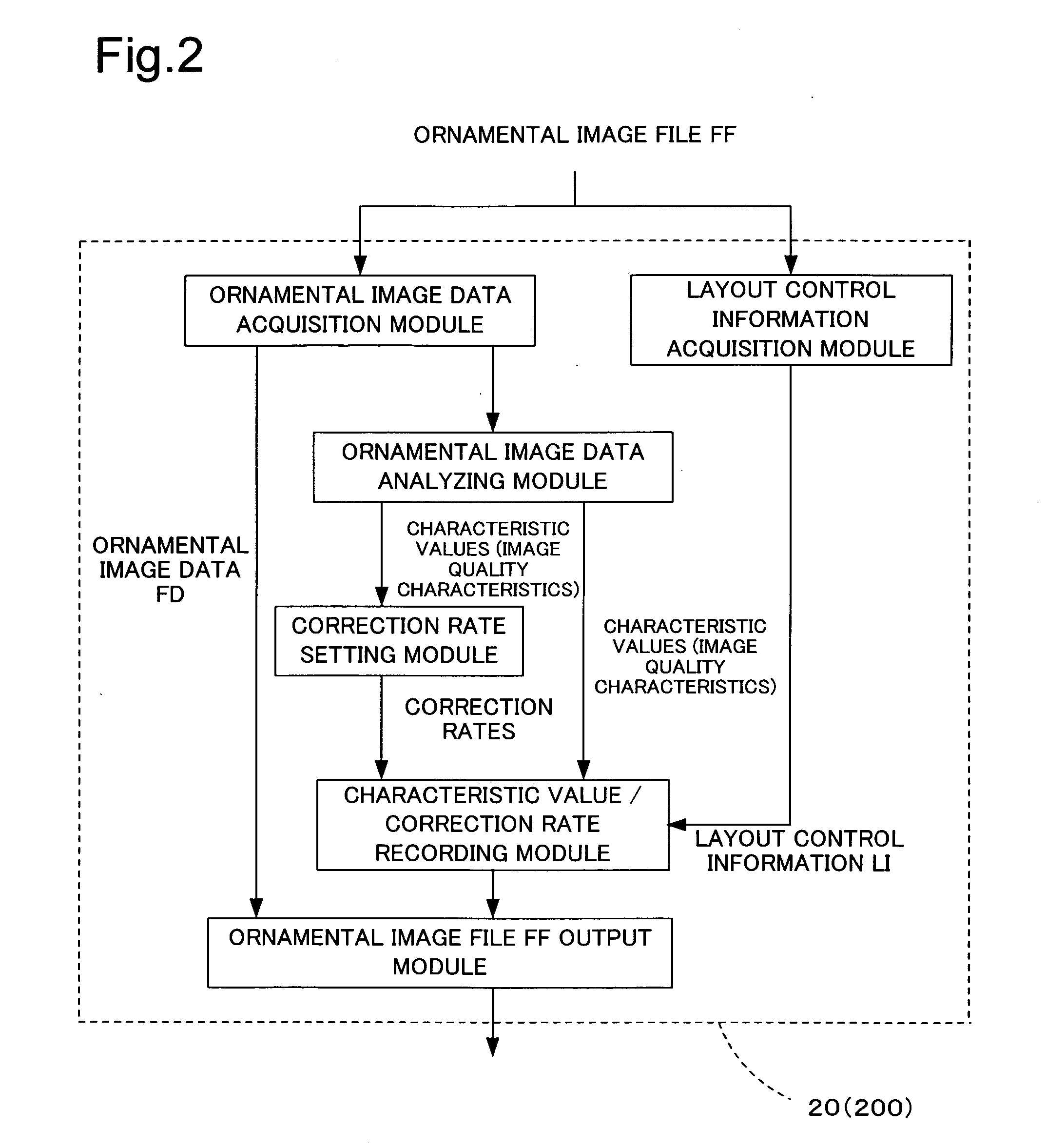
[0098] An image processing device and a corresponding image processing method in a second embodiment of the invention are described with reference to FIG. 1 and FIGS. 8 to 10. FIG. 8 is a flowchart showing an image processing routine executed by the personal computer as an image processing device of the second embodiment. FIG. 9 shows respective functional modules stored in the HDD 202 in the personal computer 20 of the second embodiment. FIG. 10 shows the file structure of an image file including image data GD and image processing control information GI. The structure of the personal computer as the image processing device of the second embodiment is identical with the structure of the personal computer 20 as the image quality adjustment information generation device of the first embodiment. The like elements are expressed by the like numerals and are not specifically described here. As shown in FIG. 9, the HDD 202 of the personal computer 200 includes an ornamental image data acqu...

third embodiment

[0127] An image processing device in a third embodiment of the invention is described with reference to FIGS. 11 and 12. FIG. 11 is a flowchart showing an image processing routine executed by the personal computer as an image processing device of the third embodiment. FIG. 12 shows respective functional modules stored in the HDD 202 in the personal computer 20 of the third embodiment. The structure of the personal computer as the image processing device of the third embodiment is identical with the structure of the personal computer 20 as the image processing device of the second embodiment. The like elements are expressed by the like numerals and are not specifically described here. As shown in FIG. 12, the HDD 202 of the personal computer 20 includes an ornamental image data acquisition module that obtains selected ornamental image data, an image quality characteristic acquisition module that analyzes the selected ornamental image data and acquires the image quality characteristic...


PUM


Abstract

A CPU 200 extracts ornamental image data and layout control information from an ornamental image file FF. When the layout control information does not include characteristic values, the CPU 200 analyzes the ornamental image data to acquire characteristic values representing a tendency of image quality of the ornamental image data. The CPU 200 may additionally compute correction rates for correcting values of image quality-relating parameters of objective image data from the acquired characteristic values of the ornamental image data. The CPU 200 writes either the acquired characteristic values or the computed correction rates into the layout control information. The layout control information including the acquired characteristic values or the computed correction rates is output together with the ornamental image data in the form of the ornamental image file FF.

Description

BACKGROUND OF THE INVENTION [0001] 1. Field of Technology [0002] The present invention relates to a technique of executing series of image processing with regard to objective image data, which has a layout location and layout dimensions relative to ornamental image data specified by layout control information. [0003] 2. Description of the Related Art [0004] There are some practical techniques of pasting objective image data, for example, image data taken by an imaging device, on ornamental image data, for example, frame image data, to output a resulting output image including an objective image surrounded by an ornamental image on a medium, such as paper. This technique uses layout control information including a script that describes a layout location and layout dimensions of the objective image data laid out on the ornamental image data. [0005] The layout control information is related to the ornamental image data. In response to the user's selection and layout of objective image ...

Claims


Application Information

Patent Timeline
Patent Type & Authority Applications(United States)
IPC IPC(8): G06K9/00G06K9/40G06T1/00G06T3/00G06T5/00G06T5/40H04N1/387
CPCG06T5/004G06T2207/20004G06T5/40G06T5/009
Inventor KUWATA, NAOKI
Owner SEIKO EPSON CORP
Why Eureka
Try Eureka