Mobile work zone protection device

Active Publication Date: 2005-06-30
STATE OF CALIFORNIA DEPT OF TRANSPORTATION
View PDF16 Cites 16 Cited by
  • Summary
  • Abstract
  • Description
  • Claims
  • Application Information

AI Technical Summary

Problems solved by technology

Each year, many highway maintenance workers are injured or killed by errant vehicles.
But for short term projects, it is impractical to use concrete barriers,

Method used


Image

  • Mobile work zone protection device
  • Mobile work zone protection device
  • Mobile work zone protection device

Examples


Embodiment Construction

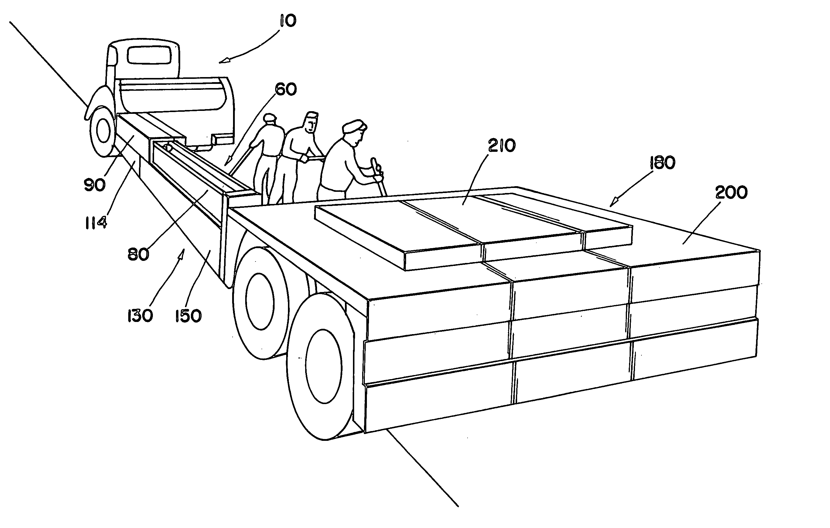
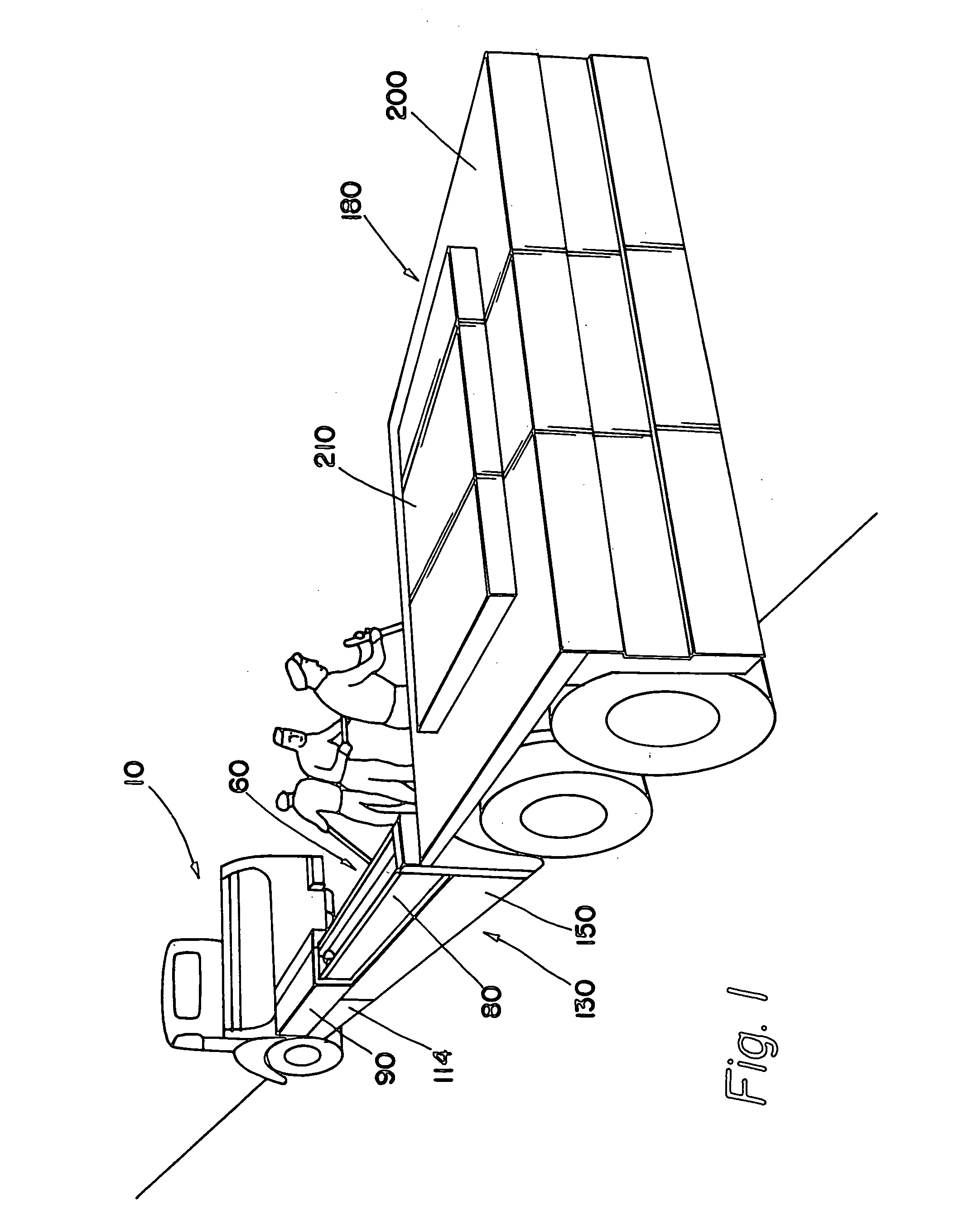
[0028] The present invention is a mobile work zone protection device, comprised of a truck 10, a front carrier 20, a barrier beam assembly 40, and a rear carrier 180.

Truck

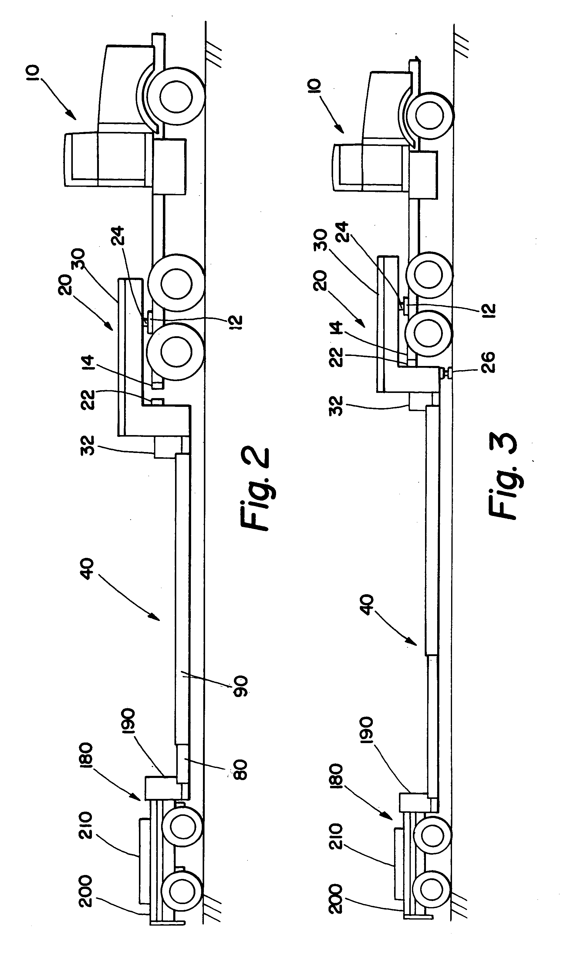
[0029] The truck 10 can be any virtually any tractor unit, with an engine (typically diesel), a driver's cab, and standard vehicle controls. The truck will have a standard “fifth wheel”12 coupling device for removably attaching the truck 10 to the front carrier 20. See FIGS. 2, 3, and 10. The fifth wheel 12 will be slidable on tracks (not shown), so that it can be moved forward or backward.

[0030] To allow deployment of the barrier beam assembly 40, the truck 10 has a hydraulic power means and a pneumatic power means. As explained below, the present invention uses hydraulic power to deploy the barrier beam assembly, and it uses air controls to lock the assembly. In this embodiment hydraulic power is provided by the truck engine using a PTO, but can also be provided by an independent or alternative engine with a ...


PUM


Abstract

A mobile work zone protection device is disclosed. It includes a front carrier, a barrier beam assembly, and a rear carrier. In one embodiment, the barrier beam assembly includes two sets of telescoping beam structures. Each of these structures can rotate from one side of the device to the other, and thus can be deployed to create a safe work zone for roadway workers on either side of the device. The structure can also be left in the transit position to provide and enclosed safe work zone.

Description

RELATED APPLICATIONS [0001] This patent claims the benefit of U.S. provisional application No. 60 / 461,347, filed on Apr. 8, 2003.BACKGROUND OF THE INVENTION [0002] 1. Field of Invention [0003] This invention relates to devices for protection of workers performing maintenance and repairs on roadways. [0004] 2. General Background [0005] Each year, many highway maintenance workers are injured or killed by errant vehicles. For long term projects, concrete barriers can be installed to create a safe work area for highway workers. But for short term projects, it is impractical to use concrete barriers, so instead cones are sometimes used to protect the side portion of the work area, and a “shadow” vehicle is often used to protect the upstream or rear area. [0006] But cones cannot stop errant vehicles that swerve into the work area, so there is a need for a mobile work zone protection device that can be deployed rapidly, and that can effectively protect workers from errant vehicles. SUMMARY...

Claims


Application Information

Patent Timeline
IPC IPC(8): E01F15/00
CPCE01F15/148E01F15/006
Inventor SCHIEFFERLY, CALVIN W.WHEELER, ANGELA E.MATSUO, JEREMY M.
Owner STATE OF CALIFORNIA DEPT OF TRANSPORTATION
Why Eureka
Try Eureka