Reusable hasp-locking mechanism

Inactive Publication Date: 2005-07-07
TRANSGUARD INDS
View PDF21 Cites 29 Cited by
  • Summary
  • Abstract
  • Description
  • Claims
  • Application Information

AI Technical Summary

Benefits of technology

[0013] The second spring may push the locking member to a p...

Problems solved by technology

However, as padlocks are susceptible to being cut with bolt cutters, numerous other lo...

Method used


Image

  • Reusable hasp-locking mechanism
  • Reusable hasp-locking mechanism
  • Reusable hasp-locking mechanism

Examples


Embodiment Construction

[0047] The embodiments disclosed below are not intended to be exhaustive or to limit the invention to the precise forms disclosed in the detailed description. Rather, the embodiments are chosen and described so that others skilled in the art might utilize their teachings.

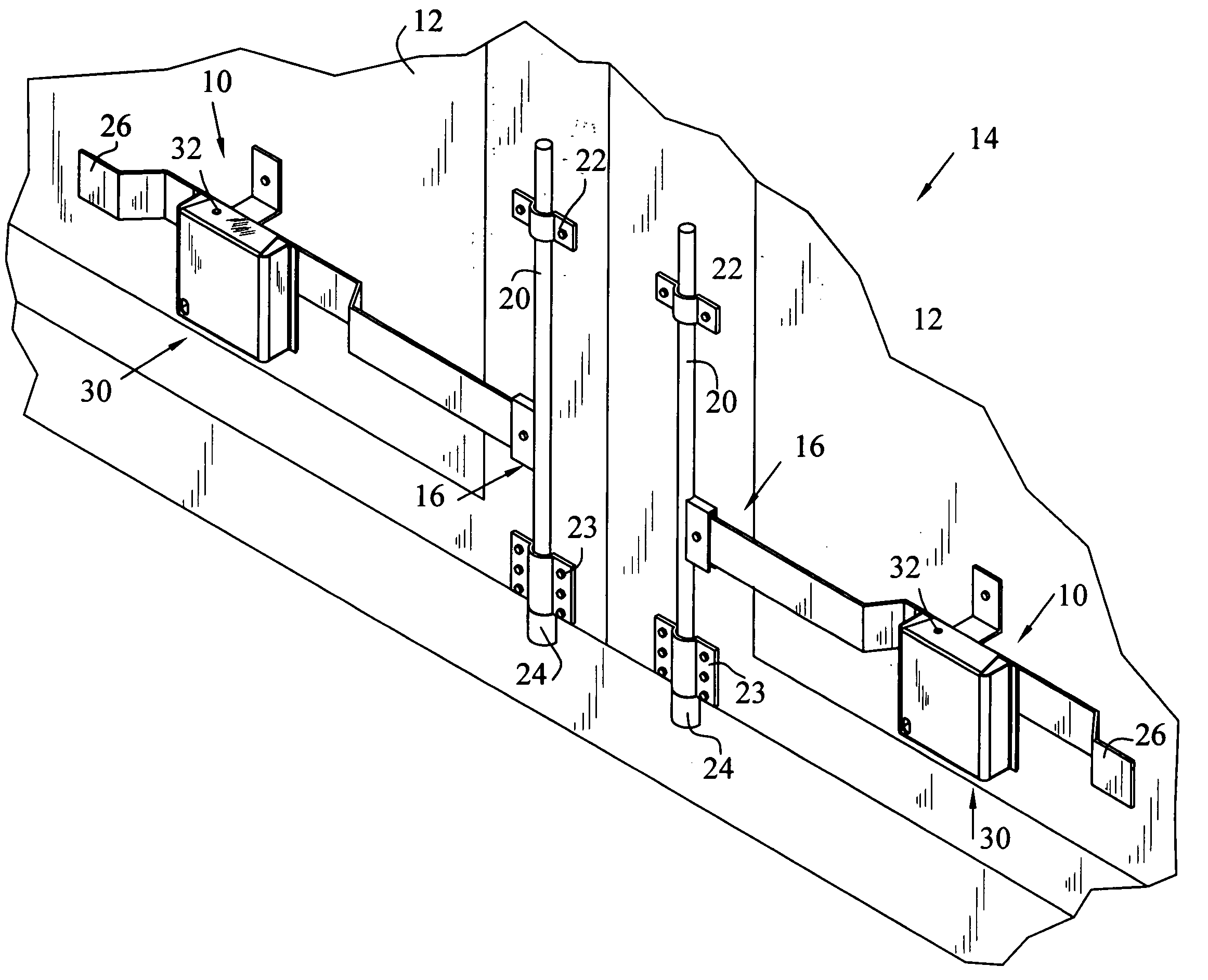
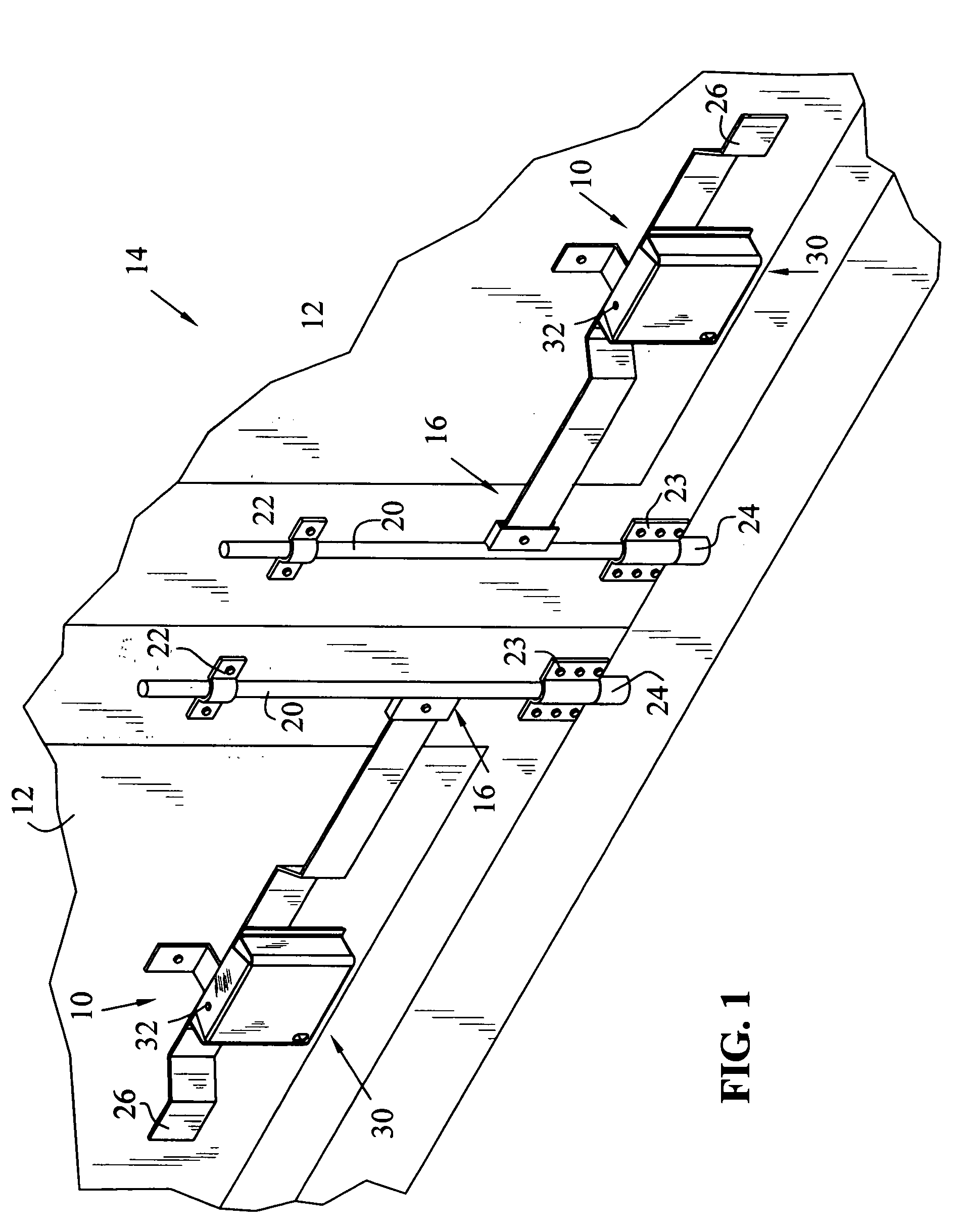
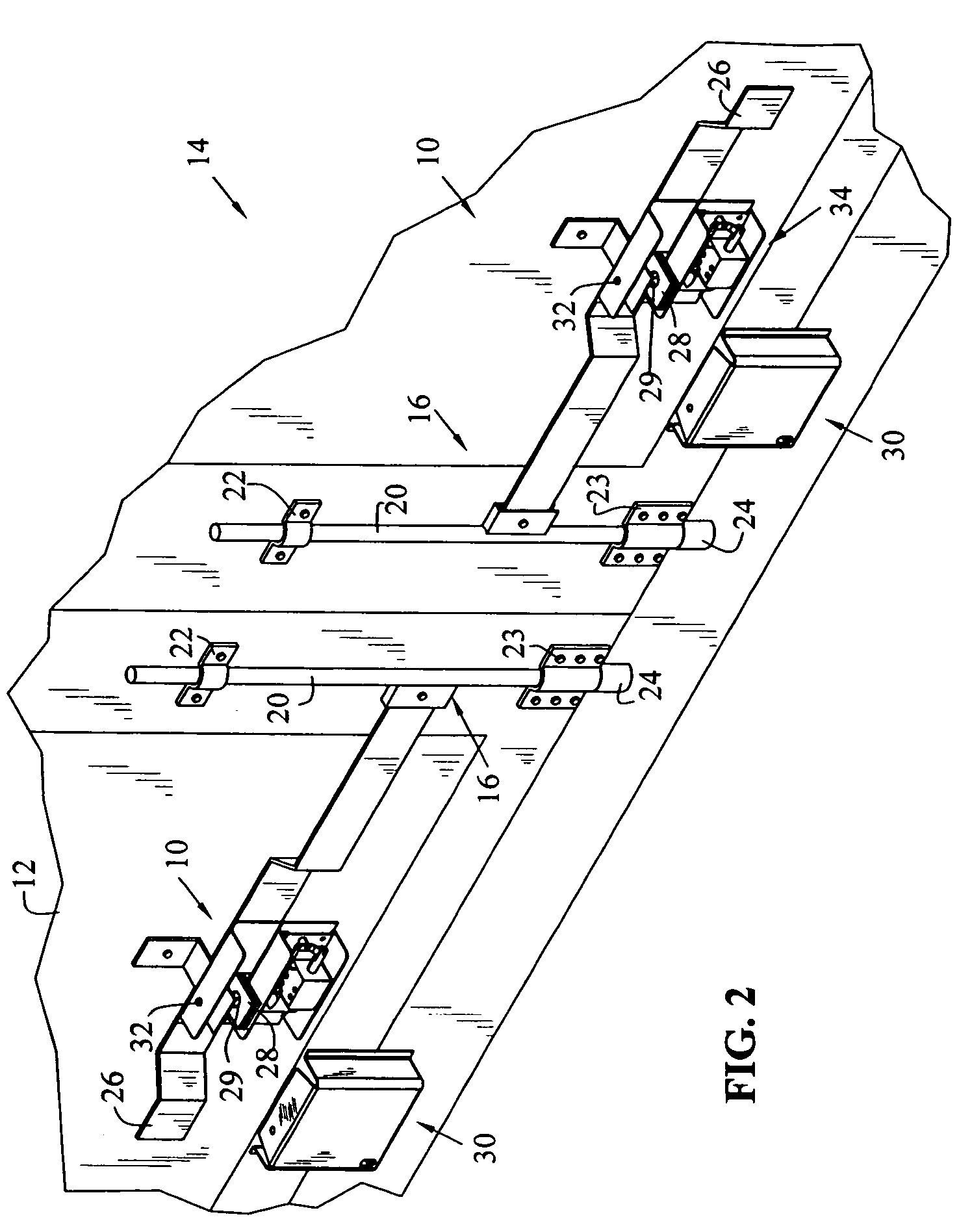
[0048] Referring to FIGS. 1-3, a pair of locking mechanisms generally indicated as 10 are shown for locking doors 12 on a vehicle or cargo container generally indicated as 14. In the embodiment shown, each door 12 includes a securing mechanism generally indicated as 16, which is well known. Each securing mechanism has a vertically moveable stanchion 20, mounting brackets 22, 23, a striker 24, a handle 26 and a hasp mechanism 28 (FIGS. 2 and 3). Hasp mechanisms 28 each include lock receiving holes 29 for use in locking securing mechanism 16 to prevent doors 12 from being opened by an unauthorized person. It should be realized that only one locking mechanism 10 may be required if one of the doors overlaps the other a...


PUM


Abstract

A locking mechanism for use on a hasp or other hardware of a door including a housing with an opening configured to receive the hasp, and a locking member that is removable from the locking mechanism during a normal unlocking operation. The locking member is insertable through at least a portion of the housing and the hasp into a locked position. The locking mechanism also includes a locking pin that is engageable with the locking member to lock the locking member in the locked position, and a spring biasing the locking pin in a first direction to lock the locking member. The locking member may have a first end and a second end, wherein the first end has a tapered surface. The tapered surface is engageable with the locking pin to push the locking pin in a second direction opposite the first direction so that the locking member may be manually inserted into the locked position. The locking member may be located predominantly within the housing when in the locked position. In one embodiment, the locking mechanism further includes a second spring, and the second spring biases the locking member along a longitudinal direction thereof when the locking member is in the locked position. The second spring may push the locking member out of the locked position when the locking pin is retracted. In one embodiment, the locking mechanism further includes an electro-mechanical device that retracts the locking pin to release the locking member from the locked position when actuated. The locking member may be manually inserted into the locked position.

Description

BACKGROUND OF THE INVENTION [0001] The present invention relates to a locking mechanism, and in particular, to a reusable locking mechanism for use on a hasp or other door hardware of a cargo container, tractor trailer doors, rail car doors, or the like. [0002] Many devices have been used to attempt to thwart tampering with or breaking into cargo containers. One of the most common prior art devices is a padlock. However, as padlocks are susceptible to being cut with bolt cutters, numerous other locking mechanisms or seals to indicate when a lock has been tampered with have been developed. [0003] One such lock and seal is disclosed in U.S. Pat. No. 5,118,149. The '149 patent discloses a breakaway security seal including a pin or shaft having a top cap and a bottom cap. The breakaway seal is protected by a hasp protector including a shield to cover the shaft in order to deter cutting the shaft with bolt cutters. When it is desired to open the container, a special seal-removal tool is ...

Claims


Application Information

Patent Timeline
IPC IPC(8): E05B13/00E05B47/06E05B65/16E05B67/38E05B73/00
CPCE05B13/002E05B39/005E05B47/0002E05B83/10E05B47/0603E05B73/0005E05B47/0004Y10T70/498Y10T70/713
Inventor BRAVO, RAMIRO H.KIEFER, SCOTT F.WARNER, JEFFREY E.HAMILTON, CRAIG B.
Owner TRANSGUARD INDS
Why Eureka
Try Eureka