Lamp containing soft-start power supply

a technology of soft-start power supply and power controller, which is applied in the direction of process and machine control, ignition automatic control, instruments, etc., can solve the problems of unstable rms load voltage conversion and rms load voltage variation in the load, and achieve the effect of increasing the duty cycle in the modulation circuit and increasing the conduction angl

Inactive Publication Date: 2005-07-14
OSRAM SYLVANIA INC
View PDF10 Cites 0 Cited by
  • Summary
  • Abstract
  • Description
  • Claims
  • Application Information

AI Technical Summary

Benefits of technology

[0018] A further object is to provide a novel method of soft-starting a power controller that uses a time-based pulse source to trigger a clipping or modulation circuit by gradually increasing a conduction angle in the clipping circuit or gradually increasing a duty cycle in the modulation circuit.

Problems solved by technology

A simple four-component RC phase-control clipping circuit demonstrates a problem of conventional phase-control clipping circuits.
Line voltage may vary from location to location up to about 10% and this variation can cause a harmful variation in RMS load voltage in the load (e.g., a lamp).
Thus, load voltage is influenced twice, once by a change in peak voltage and once by a change in conduction angle, resulting in unstable RMS load voltage conversion for the simple phase-control clipping circuit.

Method used


Image

  • Lamp containing soft-start power supply
  • Lamp containing soft-start power supply
  • Lamp containing soft-start power supply

Examples


Embodiment Construction

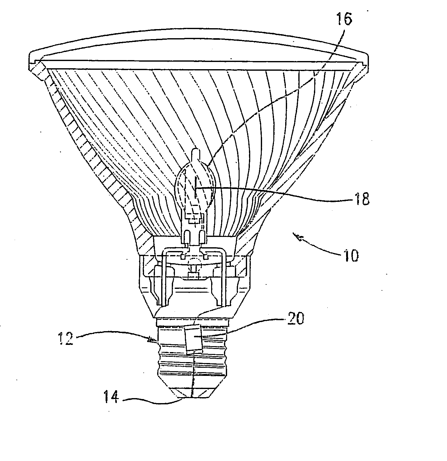
[0037] With reference to FIG. 8, a lamp 10 includes a base 12 with a lamp terminal 14 that is adapted to be connected to line (mains) voltage, a light-transmitting envelope 16 attached to the base 12 and housing a light emitting element 18 (an incandescent filament in the embodiment of FIG. 8), and a voltage conversion circuit 20 for converting a line voltage at the lamp terminal 14 to a lower operating voltage. The voltage conversion circuit 20 may be within the base 12 and connected between the lamp terminal 14 and the light emitting element 18. The voltage conversion circuit 20 may be an integrated circuit in a suitable package as shown schematically in FIG. 8.

[0038] While FIG. 8 shows the voltage conversion circuit 20 in a parabolic aluminized reflector (PAR) halogen lamp, the voltage conversion circuit 20 may be used in any incandescent lamp when placed in series between the light emitting element (e.g., filament) and a connection (e.g., lamp terminal) to a line voltage. Furth...


PUM

PropertyMeasurementUnit
voltageaaaaaaaaaa
voltageaaaaaaaaaa
RMS load voltageaaaaaaaaaa

Abstract

A lamp includes a lamp voltage conversion circuit which converts a line voltage to an RMS load voltage by clipping or modulating a load voltage. The voltage conversion circuit includes a time-based signal source that triggers conduction in the voltage conversion circuit independently of line voltage magnitude. A transistor switch whose gate receives signals from the time-based signal source triggers the voltage conversion circuit. A microcontroller increases one of a rate and a duration of the signals from the time-based signal source sent to the gate of the transistor switch when starting the lamp.

Description

BACKGROUND OF THE INVENTION [0001] The present invention is directed to a method of operating a power controller that supplies a specified power to a load, and more particularly to a method of starting a voltage converter that converts line voltage to a suitable RMS load voltage, and to a lamp with a soft-start power supply. [0002] Some loads, such as lamps, operate at a voltage lower than a line (or mains) voltage of, for example, 120V or 220V, and for such loads a voltage converter that converts line voltage to a lower operating voltage must be provided. The power supplied to the load may be controlled with a phase-control clipping circuit that typically includes an RC circuit. Moreover, some loads operate most efficiently when the power is constant (or substantially so). However, line voltage variations are magnified by these phase-control clipping circuits due to their inherent properties (as will be explained below) and the phase-control clipping circuit is desirably modified t...

Claims


Application Information

Patent Timeline
Patent Type & Authority Applications(United States)
IPC IPC(8): G05F1/00H05B39/04
CPCY02B20/148H05B39/048Y02B20/00
Inventor WEYHRAUCH, ERNEST C.KENDRICK, GEORGE B.BALLENGER, MATTHEW B.
Owner OSRAM SYLVANIA INC
Why Eureka
Try Eureka