Eureka AIR delivers breakthrough ideas for toughest innovation challenges, trusted by R&D personnel around the world.

Multipath LED driving circuit model of high power factor

A technology of LED driving and high power factor, which is applied in the field of multi-channel LED driving power supply, can solve the problems of low power factor of the circuit, large phase difference, small conduction angle, etc., so as to improve power factor, increase conduction angle, reduce The effect of phase difference

Active Publication Date: 2016-11-09
SOUTH CHINA UNIV OF TECH
View PDF9 Cites 0 Cited by
  • Summary
  • Abstract
  • Description
  • Claims
  • Application Information

AI Technical Summary

Problems solved by technology

[0004] In order to overcome the deficiencies of the above-mentioned prior art, the present invention provides a multi-channel LED drive circuit model with high power factor, which is used to solve the problems caused by large phase difference, too small conduction angle and the use of electrolysis in the prior art. The circuit power factor is low and the volume is too large caused by capacitors or transformers

Method used


Image

  • Multipath LED driving circuit model of high power factor
  • Multipath LED driving circuit model of high power factor
  • Multipath LED driving circuit model of high power factor

Examples


Embodiment Construction

[0018] Embodiments of the present invention will be described in detail below in conjunction with the accompanying drawings, so that the advantages and features of the present invention can be more easily understood by those skilled in the art.

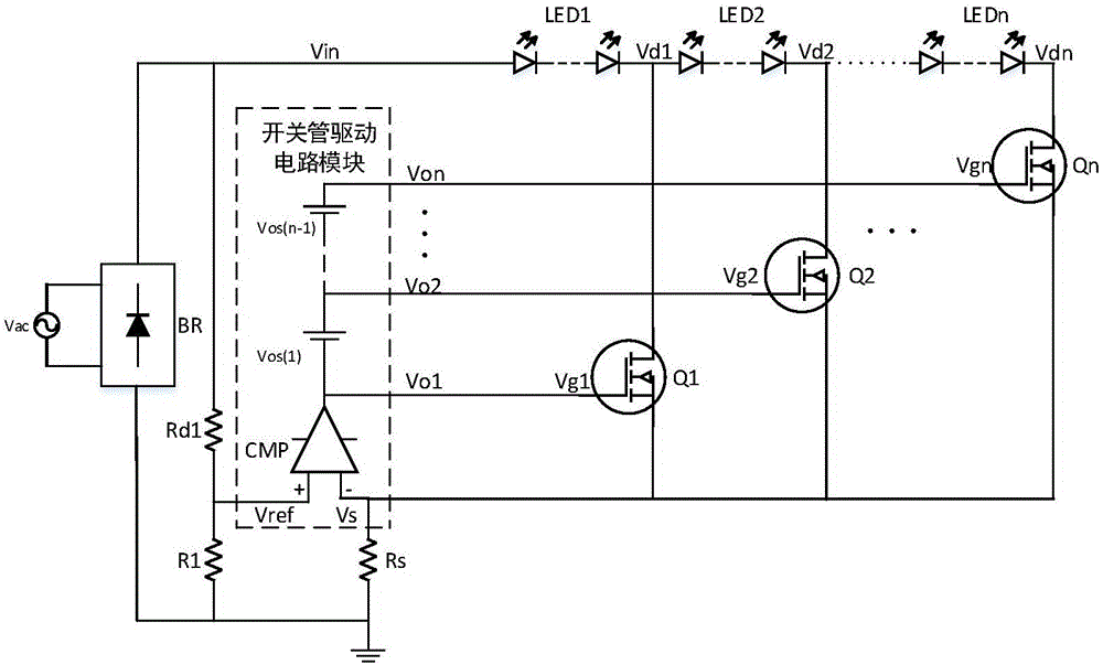
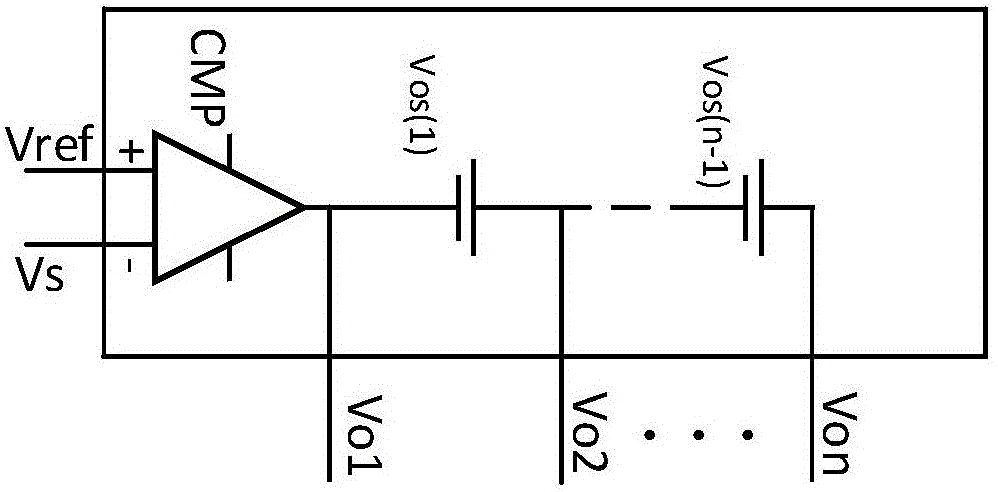
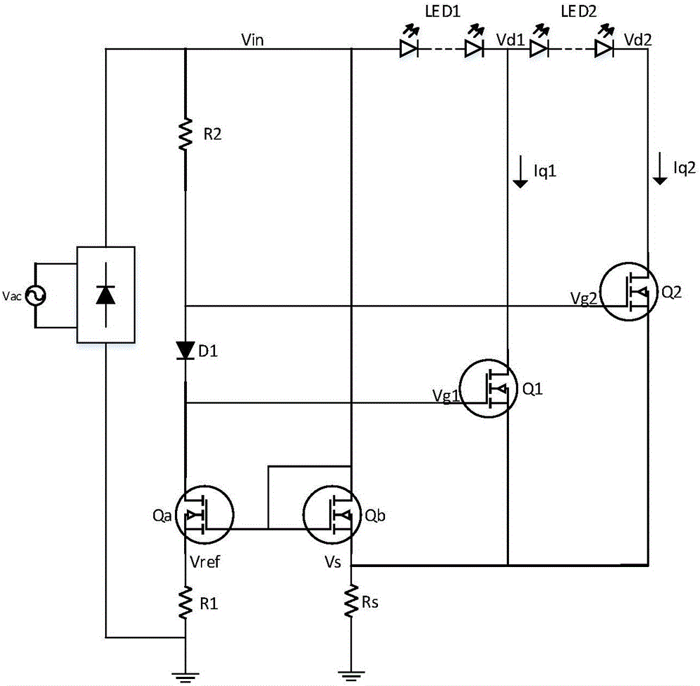
[0019] see figure 1 , figure 2 and image 3 , the embodiment of the present invention includes:

[0020] A multi-channel LED drive circuit model with high power factor, including: AC power supply, rectifier bridge, n groups of LED strings, n power switch tubes, switch tube drive circuit module, first resistor R 1 , the second resistor R 2 , Sampling resistor R s .

[0021] Such as figure 2 As shown, the switching tube drive circuit module includes a voltage comparison circuit CMP and n-1 voltage bias units (Vos 1 、Vos 2 、…Vos n-1 ), n≥1, n-1 voltage bias units are connected in series, the cathode of the first voltage bias unit is connected to the output of the voltage comparison circuit CMP, and it is the first output port ...


PUM


Abstract

The invention discloses a multipath LED driving circuit model of a high power factor. The model comprises a rectifier bridge, n LED strings in serial connection, n power switch tubes, a switch tube driving circuit module, a first resistor, a second resistor and a sampling resistor; the anode of the first LED string is connected with one output end of the rectifier bridge and one end of the second resistor; the cathode of the nth LED string is connected with a sampling voltage port of the switch tube driving circuit module and one end of the sampling resistor; the other end of the sampling resistor is grounded; a reference voltage port of the switch tube driving circuit module is connected with one end of the first resistor and the other end of the second resistor; the other end of the first resistor is grounded; and grid electrodes of the n power switch tubes are connected with n output ports of the power tube driving circuit module respectively, drain electrodes of the n power switch tubes are connected with cathodes of n LED strings, and each of source electrodes of the n power switch tubes is connected with the sampling voltage port of the switch tube driving circuit module and one end of the sampling resistor. Thus, the total harmonic distortion is low, the power factor is high, and the amount of circuit components is reduced.

Description

technical field [0001] The invention relates to the field of a multi-channel LED driving power supply, in particular to a circuit model of a high power factor multi-channel LED directly driven by an AC power supply. Background technique [0002] With the increasing awareness of global environmental protection and energy saving, the application of energy-saving technology will become more and more popular in countries around the world, especially in developed countries and regions. LED technology is a typical representative of it. LED is a high-efficiency, energy-saving, luminous The green light source with long service life is of great significance for saving energy and protecting the environment. With the continuous maturity of LED lighting technology, it will be widely used in various lighting fields. [0003] In the traditional DC LED drive circuit, constant current drive is generally used, which has the problems of large size, high cost, large harmonic distortion and lo...

Claims


Application Information

Patent Timeline
Patent Type & Authority Applications(China)
IPC IPC(8): H05B33/08H05B44/00H05B45/30H05B45/36
CPCH05B45/00
Inventor 常天海魏晓群
Owner SOUTH CHINA UNIV OF TECH
Why Eureka
Eureka Blog
Learn More