
LED drive circuit, LED constant current driver and lighting equipment

A technology of LED drive and LED lamp group, which is applied in the field of lighting, can solve the problems of large current ripple and the performance requirements of non-flicker output, etc., to expand the conduction angle, realize the effect of constant power compensation, and realize the power factor The effect of calibration

Pending Publication Date: 2022-03-01
OPPLE LIGHTING
View PDF0 Cites 0 Cited by
  • Summary
  • Abstract
  • Description
  • Claims
  • Application Information

AI Technical Summary

Problems solved by technology

[0004] However, the time-sharing conduction of LED lamps causes large current ripples in the entire power frequency cycle, which cannot meet the performance requirements of flicker-free output

Method used


Image

  • LED drive circuit, LED constant current driver and lighting equipment
  • LED drive circuit, LED constant current driver and lighting equipment
  • LED drive circuit, LED constant current driver and lighting equipment

Examples


Embodiment Construction

[0028] The following will clearly and completely describe the technical solutions in the embodiments of the present invention with reference to the drawings in the embodiments of the present invention. Apparently, the described embodiments are only some of the embodiments of the present invention, but not all of them. Based on the embodiments of the present invention, all other embodiments obtained by those skilled in the art without creative efforts fall within the protection scope of the present invention.

[0029] The terms "first" and "second" herein are used for descriptive purposes only, and cannot be understood as indicating or implying relative importance or implicitly specifying the quantity of indicated technical features. Thus, a feature defined as "first" or "second" may explicitly or implicitly include one or more of said features. In the description of the present invention, "plurality" means two or more, unless otherwise specifically defined.

[0030] In the d...


PUM


Abstract

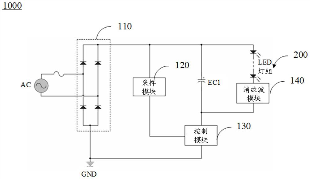
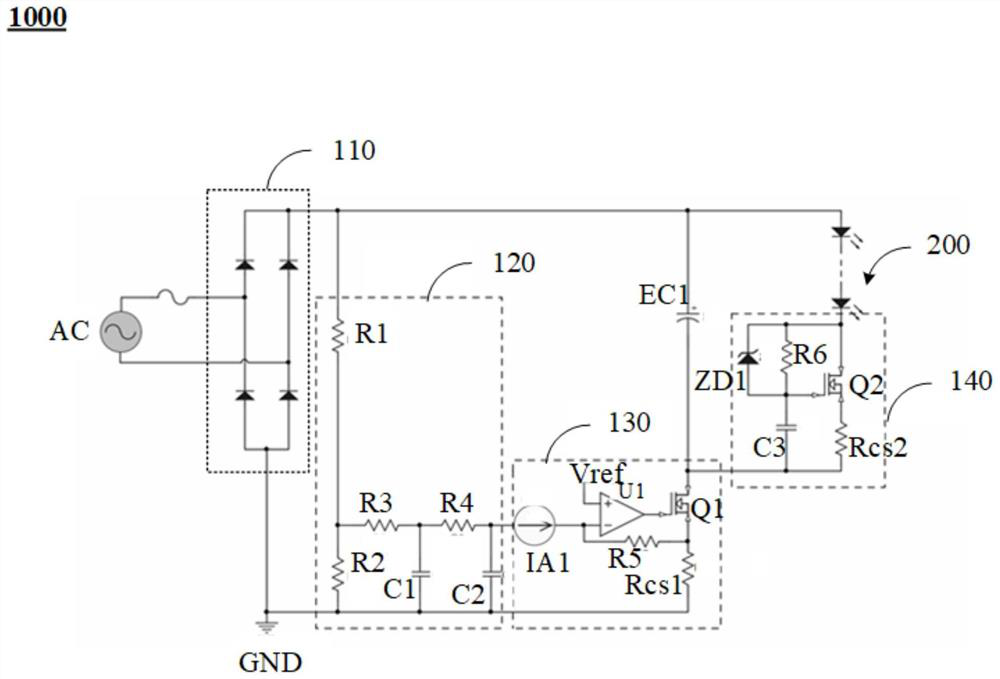
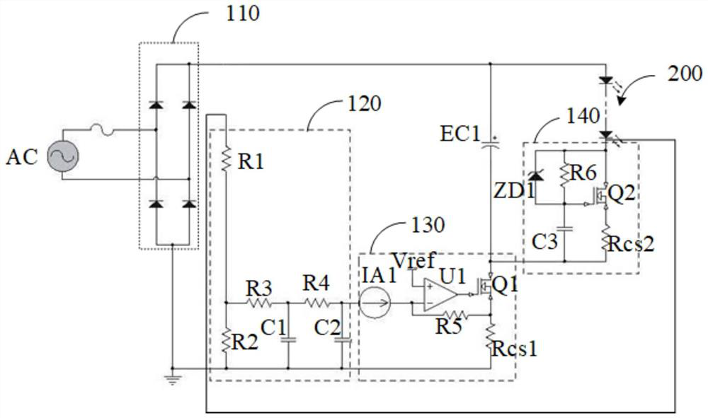
The invention discloses an LED drive circuit, an LED constant current driver and lighting equipment. The LED drive circuit comprises a rectifier module, an energy storage filter capacitor, a sampling module, a control module and a ripple elimination module. The rectifier module is used for rectifying input voltage; the sampling module is used for sampling the voltage output by the rectification module so as to output a feedback signal to the control module; the energy storage filter capacitor and the control module are connected in series between the rectifier module and the ground, and are used for charging and storing energy within the input current conduction time and providing driving current for the LED lamp group within the input current disconnection time; the control module is electrically connected with the sampling module, and is used for controlling the current of the LED lamp group according to the feedback signal and a current signal on a first sampling resistor in the control module, and controlling the conduction time and the charging current of the energy storage filter capacitor; the ripple elimination module is connected in series with the LED lamp group and then connected in parallel with the energy storage filter capacitor, and is used for controlling the current of the LED lamp group and eliminating the ripple current.

Description

technical field [0001] The invention relates to the technical field of lighting, in particular to an LED driving circuit, an LED constant current driver and lighting equipment. Background technique [0002] With the development of lighting technology, LED lights have been widely used. Before the LED lights are turned on, the LED lights need to be driven and turned on through a driving circuit. [0003] Currently, a linear drive circuit is usually used to drive an LED lamp. The linear drive circuit has many advantages, such as simple structure of circuit devices, less number of components, convenient production and debugging, convenient automatic production, and wide application in the field of general lighting. In the prior art, the multi-stage linear drive circuit is used to control the conduction of the LED lamp in time division, so that the waveform of the input current during the conduction time basically follows the change of the working waveform of the input voltage,...

Claims


Application Information

Patent Timeline
Patent Type & Authority Applications(China)
IPC IPC(8): H05B45/345H05B45/36H05B45/355
CPCH05B45/345H05B45/36H05B45/355Y02B20/40
Inventor 陈峰
Owner OPPLE LIGHTING
Learn More